This description of my methodology for aligning VCR players in absence of any specific reference material other than a sampling of commercial and home tapes. I wrote this specific to my JVC BR-S800U units. Your mileage may vary.
You probably don’t need to do alignment. And if you do, this methodology may or may not work for you. But I hope there is still useful insight here.
I did not find this task very easy, so I am publishing it in the full scope. This is not a tutorial.
Philosophy of Alignment
What is good alignment?
A tape system can be considered well-aligned when it satisfies the following practical points:
- Good playback of audio and video - good sync, good image quality, no fuzzies, there exists a sweet spot for tracking preset, etc
- Tape flows smoothly through the transport and doesn’t crease/catch/get damaged by anything
- For recording systems only: recorded audio and video signals playback on other machines adequately
Most VCR’s will play video just fine and will not damage the tape in their default state. You generally do not need to perform alignment in the first place as normal wear the VCRs experience still does not take the machinery too far out of the normal alignment.
However if you are rebuilding the machine and swapping key components around, the VCR will need re-alignment. Therefore it seems fair to say that alignment is not a thing you do to improve the quality of playback but instead a technical operation you execute when you need to re-calibrate the VCR for a known good reason. In my case I rebuilt a JVC BR-S800U from two broken units by swapping the different parts around… after swapping parts of tape deck and the video drum module around, the result was completely unaligned and unable to play tapes.
So the golden rule is don’t touch it if it works. Good alignment is when the player will reproduce the tapes. I had to re-align my player because it would not reproduce any tapes at all (the image came out corrupted)
The "effective correctness is equivalent to normative correctness" stuff must come after explanation for what is even counting as good (THAT is the basis on which everything else is pivoted). I will handle your comments however - I think it's possible to include this "effective correctness at this point may be superior" idea earlier during "what is GOOD alignment". Because that's what the reality is: the VHS system is by design containing local extrema and sits in them at its optimal, therefore our fit to local extrema is objectively satisfying the goals of good alignment while distinctly NOT satisfying normative correctness criteria, which then can be explained below in detail
What is correct alignment?
If today was not the present day, the correct way to align a VCR would be the procedures described in detail in the service manual. These procedures require use of VCR-specific jigs and special alignment tapes which will encode correct signal that embeds inside of it geometric relationships so important to the configuration of the tape transport.
This is the first kind of correctness: normative correctness. A normative-correct alignment is the one made according to the original factory references. Such an alignment embeds exactly the key geometric values of the VHS system and brings VCR to agreement with the specification as it’s printed.
Normative correctness was the correctness when the VHS format was not obsolete: the most assured way to record media that will be universally playable by assorted VCR machines was to calibrate the recording machine to normative correctness.
Normative correctness is the ideal. But factory alignment tapes are essentially unobtanium at this point. Factory jigs are rare and highly sought after. If you are very limited on resources like me, this path is impossible/too expensive/requires a prohibitive amount of effort.
However there is a second kind of correctness: effective correctness. An effective-correct alignment is the one that actually succeeds in playing back a broad sampling of VHS tapes, both commercial and home video. Effectively correct alignment has such key geometric values that they are in good coordination with the VHS standard and they result in accurate playback by the contemporary as-is device.
Effective correctness is what this methodology is aiming to attain. Not normative correctness. A VCR aligned according to the methodology presented here will be good at playing back tapes and will satisfy the requirements of “aligned well”… but it will not be a factory aligned VCR.
But today is the present and it has been many years since the VHS format became obsolete. Here is my opinion: effective correctness at this point is equivalent to normative correctness, but they are not the same thing.
With effective correctness you will still record tapes that play on modern decks - in fact those tapes might in some ways play better on modern decks than tapes recorded on good decks in 1990’s would just because everything has degraded - both the tape stock and the tape players.
In modern times, you can push VCR much harder if you aim for effective correctness over normative, since the very parts VCR is made from are no longer very normative.
Philosophy and engineering of dynamic systems
First of all, let’s talk about something very specific and philosophical. A well engineered, practical dynamic system (any machine, piece of software, any abstract design) generally exploits dynamic stability.
If there is something dynamically unstable, the engineering design calls to stabilize it. And now if something is dynamically stable (inherently so or because of a control system) then it will have a specific relation to dynamic state - be at some local extrema.
All of engineering effectively has to do with local optimization. The result is that engineered systems generally work in states which are locally optimized.
Here is how this connects to physical reality of VHS:
- The video heads must trace exact paths over the video tracks on the VHS cassette. Here is the local extrema: the resulting RF signal is at its highest when video head is aligned with the track, anything less than good alignment results in reduction of RF signal.
- The control (CTL) pulses must arrive at the exact time the video head begins/finishes the traversal of the video track. Here is the local extrema: any deviation in pulse timing will offset the video heads off the correct tracks, the only correct alignment is the one which maximizes playback RF
- Two video heads must traverse the tape symmetrically and identically. There is nothing different about them - both heads read signal identically and are functionally interchangeable. The system is symmetrical, completely. Here is the local extrema: any deviation of one head from another changes the RF signal reading. The resulting playback is at its optimal when both heads behave symmetrically. If there was any residual azimuth or offset between the video track and video head, we will immediately see asymmetry in that one specific video head
- Capstan must pull the tape at the exact rate corresponding to video tracks and CTL pulses. Here is the local extrema: if pull speed is less than required or if pull speed is higher than required, then there is a constant shifting offset between the video heads and video tracks. This results in loss of stable RF and instead we get long-duration pulses (whenever heads ‘slide off’ the video track and show us the space between video tracks)
- Hi-Fi signal should be largely close and almost in-phase with linear audio signal. Here is the local extrema: these signals are synchronized during the recording, so any time offset during playback suggests that the geometric distance between the video drum (Hi-Fi audio) and the A/C head (linear audio) is incorrect.
So here is the fundamental statement on which this methodology is based on: VHS system in its aligned state sits at the local extrema by some key measurable parameters.
Therefore we can perform a alignment of a VCR by iteratively pushing it towards the local extrema using the commercial video tapes as a reference.
So what do I do?
In order to effectively repair a VCR you must understand the physics behind how everything works. How the servo system works, how the video head reads data off the tape, etc…
Explaining this is beyond the scope of the current document. That is the knowledge that should be obtained in parallel with this if you really do attempt something like this.
The short version of methodology is given first and I wrote it to be a reference for actually doing this work in practice. But the longer elaborate version is mandatory for understanding what to look for and why the methodology works - it helps at every step of the way if you build up intuitive sense of how the VCR works and what constitutes a malfunction when it comes to the tape transport system.
Centroid Methodology
Preliminary
The centroid VCR alignment methodology is based on iteratively (in repeated steps) bringing a misaligned VCR towards more and more fine alignment. The use of multiple commercial and home tapes establishes a centroid of alignment - all of these tapes are individual points in the alignment record (as the geometry of video and audio tracks on the tape encodes the alignment of the recording VCR) and our goal is to find such a point that sits at the local extrema along all of our measured variables and mechanical adjustment parameters.
For executing this methodology you need a sampling of commercial tapes with good and mediocre alignment (a lot of old Disney tapes are a good source of good alignment reference, while any tapes whatsoever can do for mediocre alignment reference).
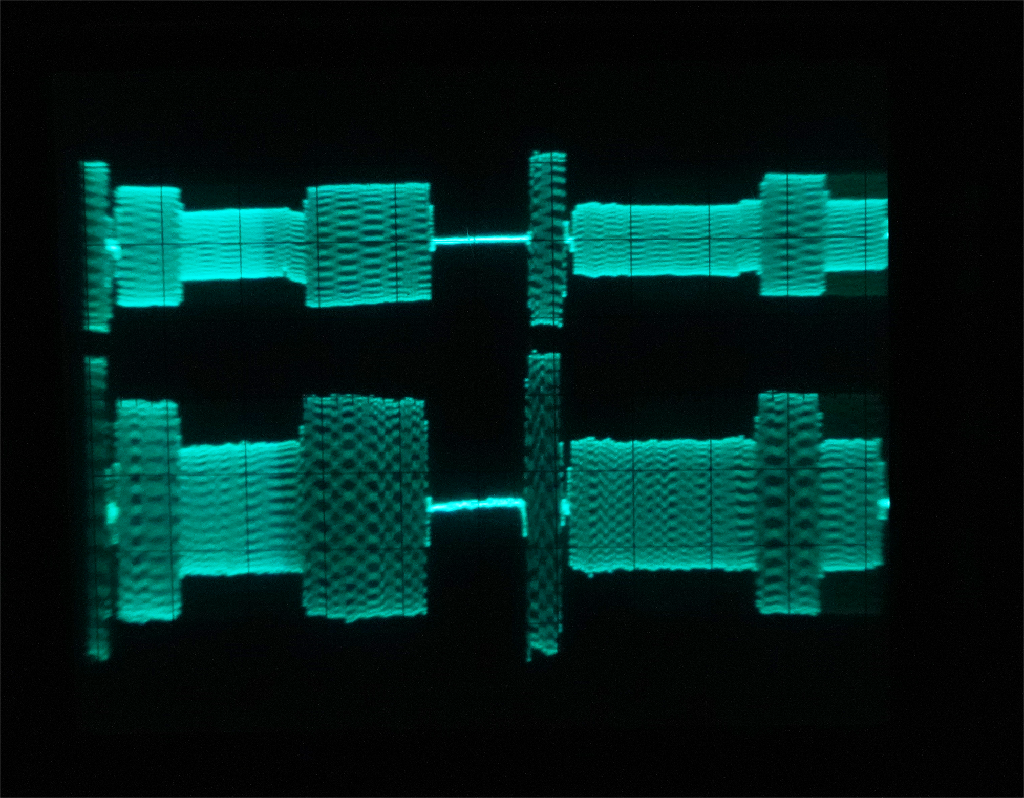
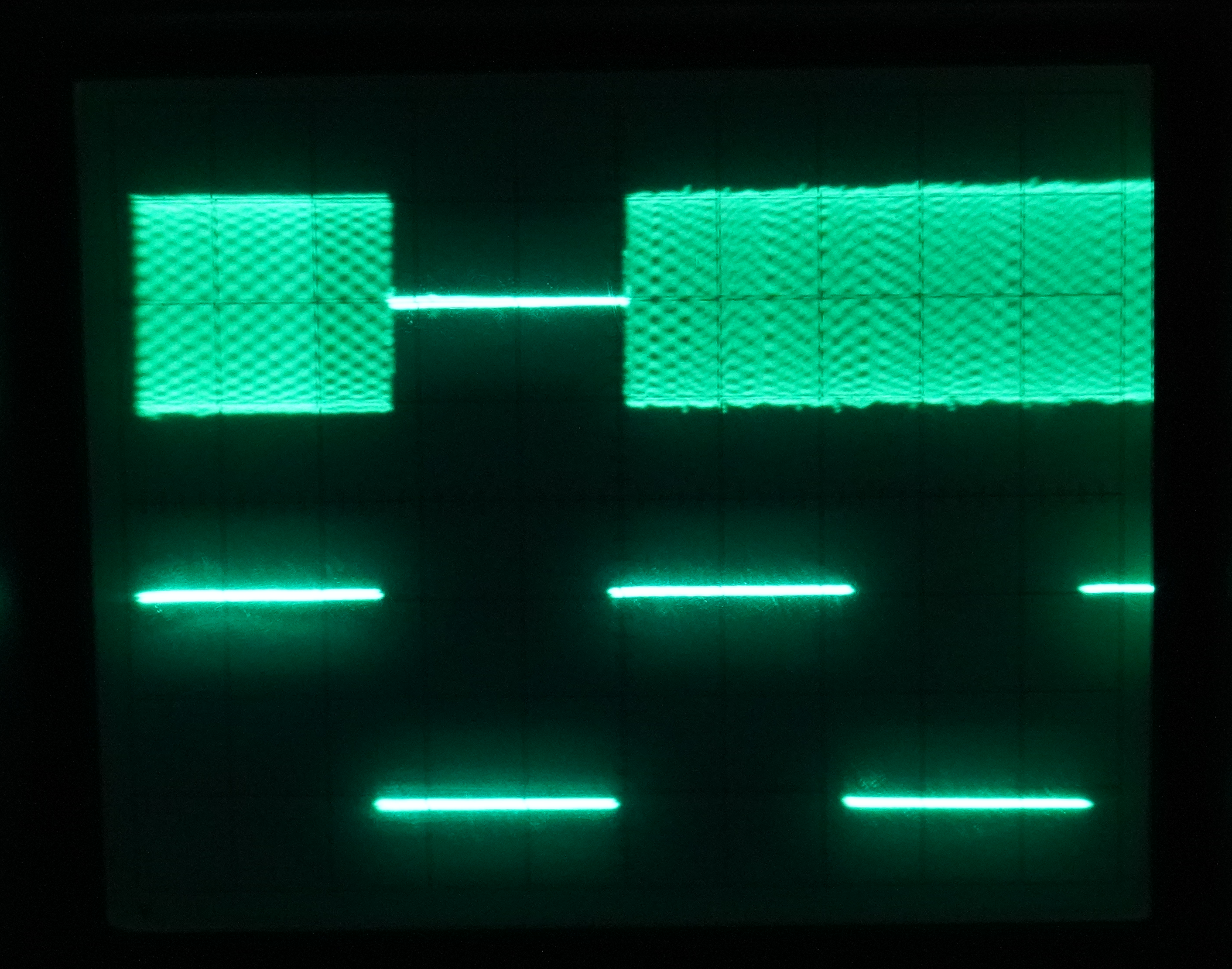
You also need an oscilloscope in order to sample test points inside the VCR. There is a need to monitor accurate output over time of many different signals: the head switching signal, playback FM RF signal from the video heads, CTL signal from the control head, linear audio left/right stereo.
You will need a sacrificial tape - the one that will be used to perform initial alignment and the one that is permitted to be damaged.
Theory: Video Head Drum
This chapter describes the physics of video head crossing over video tracks and how this geometry is affected by take-up and supply side guide rollers
Theory: Tape Flow
This chapter describes the physics of how the VHS tape interacts with guide rollers and the stabilizing purpose of rollers (some rollers stabilize tape from the top, some stabilize tape from the bottom), plus explanation for each roller that is NOT involved in further detailed tape flow adjustments but still must be performed.
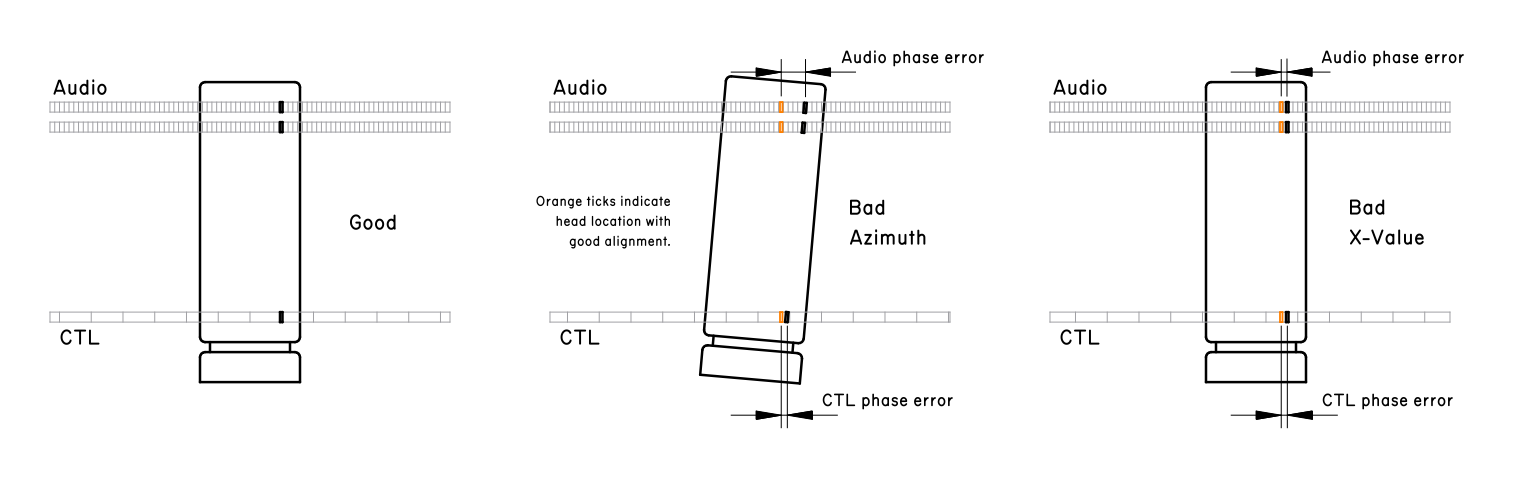
Theory: X-Value and CTL Track
Theory: Azimuth and Tilt of A/C Head
Justification
This chapter provides justification for this methodology, talks about several types of invariants used as external reference in iterative process:
- Machined constants - defined by machined physical geometry, arrangement of atoms in the VCR, the aging does not wear these down really. Hard ground
- Recorded geometry - imprint of a calibrated (or not so much) system, no single imprint can be used as absolute reference due to presence of a residual (both bad calibration and aging of the recording machine etc) but a family of them has a clear centroid - a centerpoint of all alignments
- Relative reference - these are driven by physical processes, for example tilt of the A/C head relative to the tape can only be set by a template (setting a normative value - not necessarily the best one!) or by iterative methodology as presented here (in which case it simply arrives at best fit by iteration). In this case maximization of output is rooted in maximizing the efficiency of physical processes of playback/recording/etc of the VCR
These are the general alignments:
1. Drum / tape-path geometry (tape-vs-drum alignment)
tape-path-vs-drum alignment
← FM envelope uniform across the head-switching point at tracking zero
← video heads trace the helical tracks at the geometry they were written at
← [MC] drum diameter + head-tip projection + wrap angle (machined) AND
← [RA] helical track angle/pitch as physically written on Disney tape
2. Tracking zero point
tracking zero
← PB FM amplitude is maximal/uniform when CTL-derived servo phase = nominal
← the tracking knob is a calibrated phase offset of CTL-derived servo timing
← CTL pulse edge timing as physically printed on the tape
← [RA] CTL track position + pulse spacing on Disney tape (one pulse per frame, format-fixed rate)
3. Drum / head height (drum-related height adjustments)
drum height adjustments
← FM uniform at tracking zero with no vertical track-walk
← video head vertical entry point matches written track vertical position
← [MC] drum mechanical height (machined) AND
← [RA] track vertical position on Disney tape
← [MC] tape width (slitting standard — the tape edge is the vertical datum)
4. Head-path parallelism to video tracks (skew / no residual)
head-path parallelism
← FM amplitude changes uniformly across the full tracking sweep (no lopsided bowl)
← video head path is parallel to the written track direction
← [MC] head-tip geometry + drum scan plane (machined) AND
← [RA] written track direction on Disney tape
5. A/C head height (L/R linear audio)
A/C head height
← L/R linear audio amplitude equal and at local maximum
← both audio gaps centered on their respective tracks
← [MC] audio-gap spacing on the A/C head stack (machined) AND
← [MC] tape width / audio track position (format slitting + record-head geometry)
← (soft cross-check) [RA-ish] 0 dBu pin: level lands where a correct deck puts it
6. A/C head azimuth (L/R linear audio phase)
A/C head azimuth
← L/R linear audio phase matched (sub-cycle null)
← audio gap is perpendicular to tape travel (no gap rotation)
← [MC] tape travel direction (transport geometry, machined) AND
← [RA] phase relationship as written on Disney/reference tape
← (planned upgrade) coarse vernier marker resolves absolute (integer-cycle) offset
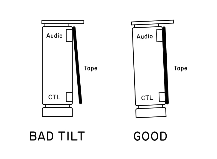
7. A/C head tilt (forward bent)
A/C head tilt
← CTL + linear audio both near groove optima (eagerness-to-seat maximized)
← all three gaps make even contact across the stack (carrier pose of minimum strain)
← [MC] A/C head stack geometry (machined gap positions) AND
← functional: clean tape flow at ~100x shuttle, zero imperfections
← [MC] tape mechanical behavior between A/C head and next guide (the tape IS the check plate)
8. CTL pulse amplitude / slice margin — RELATIVE ONLY
CTL amplitude
← CTL pulse clears the trigger/slicer with margin
← conditioned analog CTL level at the pre-slicer test point
← head contact x record current x tape (emergent product, none of them specified)
← [RR] "a known-working slice margin on the healthy reference deck"
← ... and nothing further. There is no absolute below this.
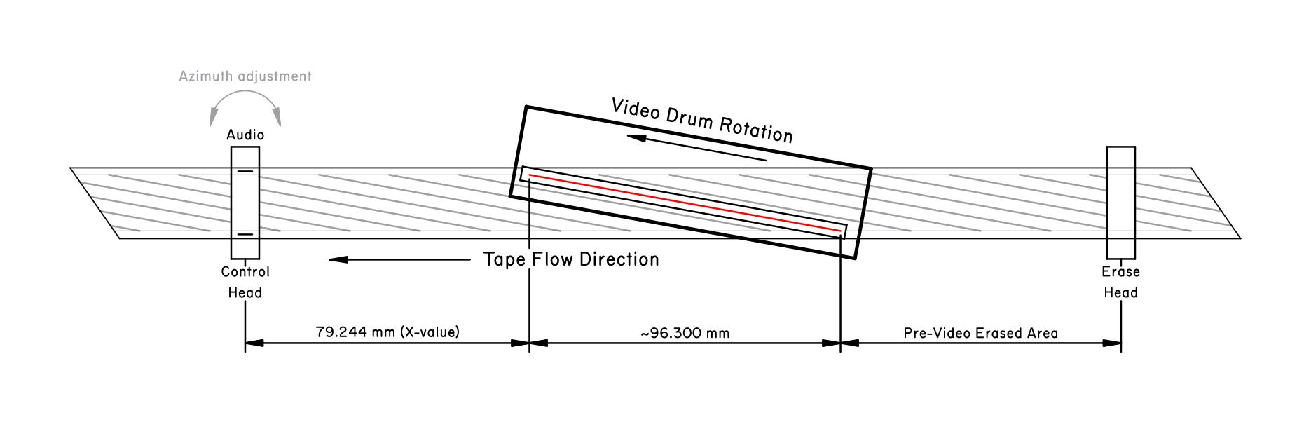
9. X-value (taper nut — longitudinal A/C head position)
X-value
← picture-to-linear-audio timing offset matches format standard
← physical spacing between video drum and linear audio gap / tape speed
← [MC] drum-to-A/C-head longitudinal distance (taper-nut position, mechanical) AND
← [RA] the standard offset as printed (sync-tied reference tape, when one exists)
← [MC] tape linear speed (capstan + format standard)
The dependency spine: tape edge and drum
Two machined constants sit underneath almost everything vertical and rotational:
[MC] TAPE WIDTH / EDGE (slitting standard)
└─ vertical datum for: drum height (#3), A/C head height (#5),
and implicitly the track positions every FM/audio reading references
[MC] DRUM (diameter + scan plane + head geometry)
└─ read-geometry datum for: tape-path-vs-drum (#1), tracking zero (#2),
head-path parallelism (#4), and the timing half of X-value (#9)
Order of operations
The methodology only needs rough justification for order of operations. Here it is:
First we perform video drum tape wrapping adjustments, because those depend solely on mechanics of the tape flow and they are our primary measurement tool
Then we align A/C head because a coarse alignment of A/C head is required to start adjusting anything else
Then we refine alignment of A/C head because after we get coarse alignment we can actually adjust A/C head tilt perfectly, then adjust azimuth to perfection to best of our ability
Then we finally can adjust X-value because now A/C head has trusted angular rotation (may have a consistent error still baked in, but we trust that error will not impact us for our small adjustments of X-value during this iteration)
Then we can finally refine A/C alignment to perfection, since we now have a coarse estimate of the right X-value
And finally we once again refine X-value because it’s the most subtle element (depends on tracking sweep bowl symmetry and such) - we leave the most vague, subtle operation at the end due to its smallest effect on other cross-coupled variables
Methodology
This chapter contains a table for each entry containing the following columns:
- Step number
- Short description of what’s done in this step
- What derivative must be monitored and over what range (e.g. derivative of PB RF signal envelope over varying the tracking knob, variation of CTL pulse amplitude over varying the tilt bolt etc)
- What is the physical process which explains what we are doing and what we are seeing during our adjustments
- How do we know this step is done/finished?
Some steps roughly illustrated:
- Coarse tape flow adjustment
- Alignment of tape around the video drum
- A/C head first alignment (coarse initial)
- Refinement of tape around drum till goodness is reached
- Show method for verification of tape wrap AND A/C head alignment correctness using the tracking sweep symmetry
- A/C head second alignment (refined initial alignment)
- CTL and linear audio based tilt calibration
- A/C head X-value adjustment based on tracking sweep
- A/C head refined alignment
- A/C head X-value refinement and verification
- Verification of X-value using linear vs hifi audio phase offset
- Final verification of the entire system
Short-circuits
These are short-circuits I employed myself, but they are conditional on having extra resources:
- Having multiple VCRs -> create alignment record and use it for cross-checking
- Find VCRs with still factory alignment -> create alignment record tapes to use as reference for what factory alignment is and skipping over all coarse alignment
- Record your own special tapes with correct signals -> if you can trust the recording VCR, this becomes a super useful tool
- Cross-check across many VCRs gives much more confidence
Alignment-record is fulfillment - and this is a thought very worthy of being put into the blog post. So here’s what it feels like: at first I had this pile of VCR’s. How do I know which ones are good? How do I know which ones are bad? What’s good or bad?
But here’s what aligning this VCR taught me: the shape of VHS systems dynamic space (“VHS system” referring to normative alignment of an ideal VCR as well as cumulative experience of best practices of how a VHS system should work) is actually very benign and tolerant. It has some sharp cliffs and borders, but actually it has this weird hyperbolic behavior: at initial coarse alignment, most coarse adjustments will coarsely change measured variables.
At first everything affects everything pretty equally. The space feels linear but without any clear resolution points.
Then once you get a few basics right - the right adjustments of supply and take-up rollers around drum for example, once you can get things roughly where real alignment might sit (the video heads loosely cross over video track mostly along with it etc) suddenly the system gains highly hyberbolic property - large adjustments will result in little effect until they suddenly result in a lot of effect.
This shapes the space in a weirdly cozy way - once you get initial coarse variables right, you’re hunting for these sharp subtle points. You keep crossing these narrow points of extrema (and they are narrow but the slopes are very benign - so you very clearly see them on oscilloscope, but they are easy to hit even with shaky hands after you learn a bit of finesse) over and over, and the more you work on it, the more often you start crossing them… Finally you start hitting point where suddenly adjustments seem to be diminishing in effect again. You bring all parameters narrowly to the good middle alignment so the natural random variation between tapes, the total ellipsoid surrounding the points in which we find the centroid - these things become dominant. You reach the residual you can’t decrease anymore because it randomly changes between both different tapes and inserting same tape over and over again.
This is where the method stops if you really keep running it