I want to study my centroid methodology more conveniently and later prove formally that what I came up with actually results in aligned VCRs. So I have been working on a physics model of the VHS playback - specifically the impact of mechanical aspects of playback on the RF envelope read by video heads.
» The VHS playback simulator can be accessed here «
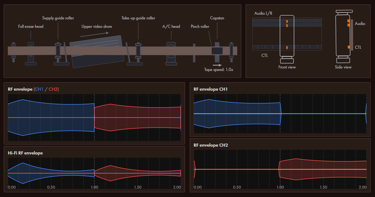
I’m not that good at HTML, so it’s just kludged together for the most part… but I think I fixed the most embarrassing HTML-related bugs by now.
This is effectively a purely geometric model with just basic physics - a very simple, idealistic reflection of what happens inside the VHS playback. The simulator calculates the following things:
- How geometry of tape wraps around the drum
- How the video heads pass over video tracks on the tape during rotation
- The basic operation of the servo circuit and how CTL pulses are used
- Simple model of the audio/control head that reflects how X-value, azimuth and tilt all impact the output signals
- Simple model of linear and Hi-Fi audio which shows phase relationship between the two depending on the adjustments of the A/C head
- Basic physics of azimuth rejection that ensure the signal from nearby tracks does not interfere with the track being currently read
- Both EP and SP mode are supported, showing how much more sensitive the EP mode is to alignment (see this post 0014 for more information)
VHS Simulator Quick Reference⌗
The VHS simulator will output the following indications, naming from top to bottom:
- Graphic indication of the tape transport path. A schematic indication illustrating the alignment of the tape to the video drum, position of the A/C head. All distances exaggerated
- Graphic indication of the A/C head alignment - azimuth, X-value offset, tilt
- RF envelope - predicted RF envelope as seen after the head amplifier of the VCR
- Hi-Fi RF envelope - predicted Hi-Fi RF envelope that accounts for narrower width of the Hi-Fi track
- Head switch pulse - shows signal that selects which head is connected to the amplifier. See also “head switch offset” parameter
- CTL pulses - simulation of the CTL pulses as read by the A/C head
- Relative audio phases - 10x zoomed in view of the Hi-Fi, linear audio left and linear audio right waveforms. This indicates the relative phase between all of these signals, which will vary with X-value adjustments and A/C head azimuth
- RF envelope CH1 - output of the CH1 video head, including the dead zone when it is not touching the tape
- RF envelope CH2 - same for CH2 video head
- Linear audio R - right channel of the linear audio track (shown at the same scale as the RF envelope)
- Linear audio L - left channel of the linear audio track
- Hi-Fi audio - audio picked up from the Hi-Fi system. The audio will vanish if Hi-Fi is predicted to not have been reliably established
Underneath there is a list of parameters for the model that can be edited and the tracking meter (I couldn’t really fit it anywhere else). The tracking level meter is made to work the same way as it does on my BR-S800U - it shows the integrated RF envelope.
This is a short reference for all the model parameters, see below for a more detailed explanation of the physics involved:
| Parameter | Description |
|---|---|
| Playback mode | Selects between SP or EP playback mode (EP tape runs at 1/3rd of the rate the SP does, the tracks are much more narrow and the EP video heads are accordingly adjusted) |
| Tape speed | Current tape playback/shuttle speed. 1.0x means normal playback, 0.0x is still mode, -1.0x is reverse playback mode |
| Tracking knob | Tracking adjustment knob - allows adjusting tracking same way it works on my BR-S800U (offset by one SP track width - in EP mode it crosses over multiple tracks) |
| Supply offset | Vertical offset of the supply side tape guide pole. Adjusts how the tape enters the video drum |
| Take-up offset | Vertical offset of the take-up side tape guide pole. Adjusts how the tape leaves the video drum |
| X-value adjustment | Offset along the direction of tape flow of the A/C head position that defines phase relationship between CTL pulses and video track positions |
| Head switch offset | Allows adjusting where the VCR performs a head switch. It’s mostly just illustrative of the mechanic, it is usually supposed to be set to 0% |
| A/C head tilt | See A/C head graphic for visual illustration of the tilt angle. Affects how well the tape comes in contact with CTL head and linear audio R/L heads. Very simplistic modelling just for illustrative purposes |
| A/C head azimuth | Azimuth of the A/C head. See graphic. Affects the phase relationship between CTL, linear audio R/L tracks. |
| A/C head height | Vertical height adjustment of the A/C head that models the vertical misalignment between the A/C individual heads and the tracks on the tape |
| CH1/CH2 azimuth error | Azimuth deflection of the video head (see “azimuth scanning loss” chapter for more details) |
| CH1/CH2 gain | Additional gain in decibels for the specified head (no specific physics meaning - just allows adjusting amplification for both heads individually) |
| CH1/CH2 height | Height/altitude offset of the video head. This is vertical offset along the drum rotation axis - maps to lateral offset between the head and the video track |
| CH1/CH2 protrusion | Distance by which the video head sticks outside of the normal diameter of the video drum. This causes the heads to come in contact with tape earlier and leave contact later, additionally skewing the time base of the actual FM segment that ends up in the head switching window for that head. Negative values correspond to severe head wear, indicating that head has “receded” closer into the drum |
| Recorded signal type | Which audio signal is recorded on the tape (stereo L/R tracks plus Hi-Fi). Allows to select sine wave or the pulse coded sine wave for absolute phase determination. The pulse coded (AM-modulated) sine wave will illustrate the phase offset in absolute terms where normal sine wave cannot. |
| Recorded signal frequency | Base frequency for the recorded signal. This affects azimuth scanning losses for the audio heads due to A/C head azimuth, the visual display of the signal and have some effect on the amplitude of the audio signal due to linear audio response curve (in current simulator the response curve is assumed for SP recording) |
Model Description - Time Around Drum⌗
The main input variable of the entire model is time around the drum (TimeAroundDrum a.k.a. tau). It is a unitless measure of both time and space dependencies in the movement of the video drum:
- CH1 video head begins to touch tape at 0.0 tau - the supply-side contact point
- The video drum performs first half-rotation, scanning the first field
- The CH1 head leaves tape at 1.0 tau, CH2 head begins to contact tape at the same time. CH1 leaves at take-up side, the CH2 enters at supply side
- The CH2 head scans across the tape as drum performs second half-rotation, scanning the second field
- CH2 head leaves the tape at 2.0 tau
The explanation above is somewhat simplified - actually CH1 head begins to contact tape slightly earlier than 0.0 tau and stops contacting tape slightly later after 1.0 tau (because tape is wrapped by more than 180 degrees around the drum!). This slight overlap allows to establish a truly seamless switching between the two channels and create a continuous FM signal.
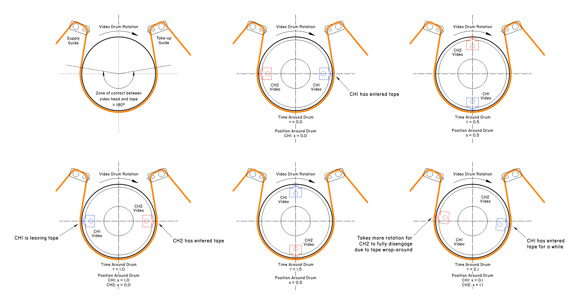
The range of 0.0 to 2.0 tau represents the full single rotation of the video drum. Because the system is mechanically coupled, during normal operation of the drum “time” and “angular position of the drum” mean the same thing.
The position around the drum (PositionAroundDrum) is almost the same value as TimeAroundDrum, but brought to a normalized range of -0.5..1.5 to represent exact geometric position of video head around the span of rotation and around the VHS tape itself.
Time around the drum is used as “time” input to the model (for drawing RF envelope and audio signals over time), with “position” being calculated from it for each of the video heads.
Model Description - Video Head Scan Model⌗
To calculate the RF envelope a very simple geometric model is used. Based on a variety of the parameters, the lateral offset between the video reading head and the video track is determined.
The lateral offset is measured perpendicular to the video track, effectively it is the deviation between the video head and the nominal video track (the video track that the video head would read in properly aligned conditions).
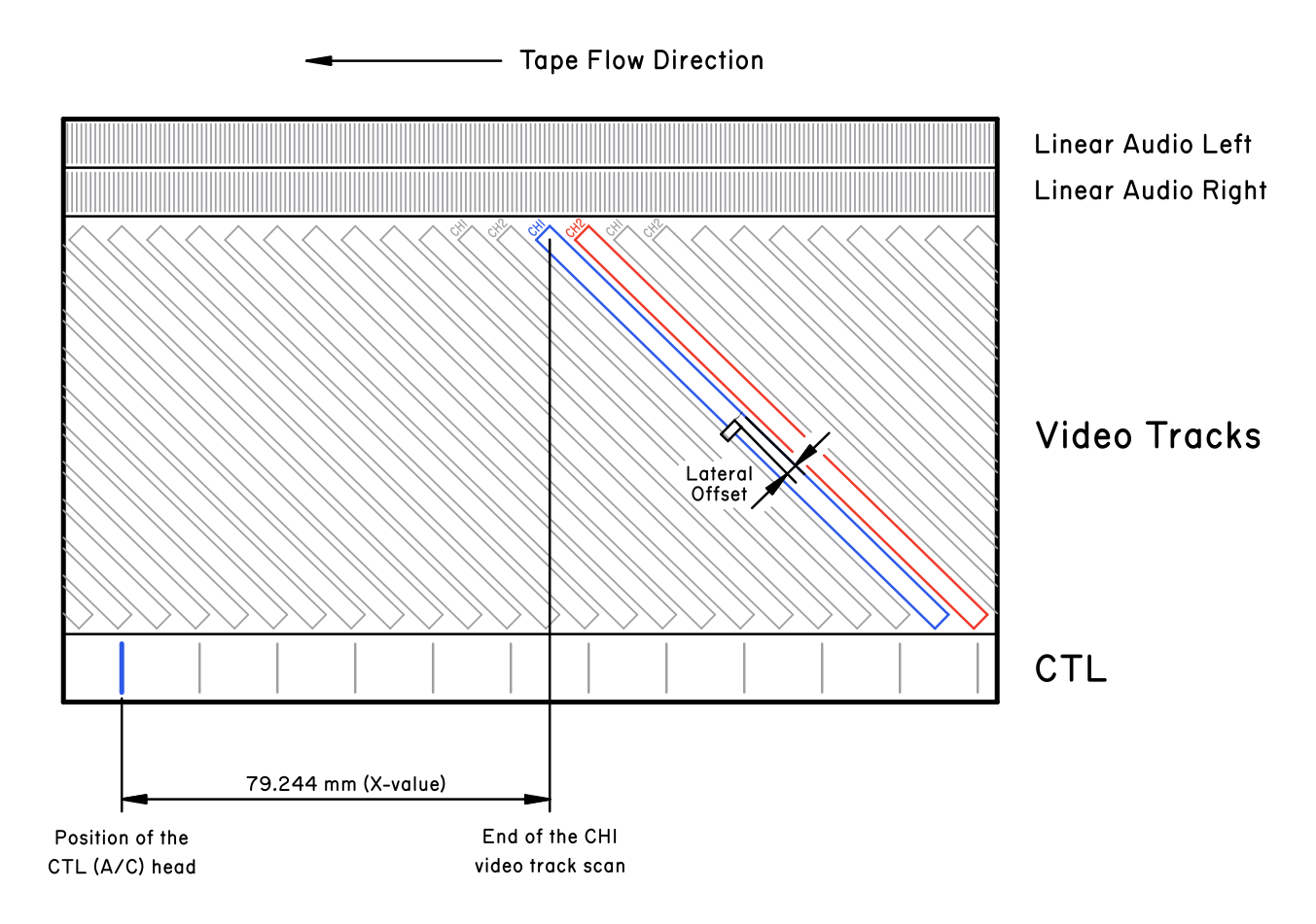
The lateral offset is used to determine how much of the video head actually overlaps with the video track. The signal attenuation due to misalignment is taken proportional to the amount of overlap between the video head and the video track.
The lateral offset is a sum of the following factors:
| Offset | Formula | Description |
|---|---|---|
| Supply Guide Lateral Offset | GuideSupplyOffset * exp(-s/const) | Lateral offset due to supply guide adjustment, with mechanical relaxation across the drum span. |
| Take-up Guide Lateral Offset | GuideTakeupOffset * exp(-(1-s)/const) | Lateral offset due to take-up guide adjustment, with mechanical relaxation across the drum span. |
| Bow Offset | Bow * s * (1 - s) | Parabolic bow due to stretching/elastic response of the VHS tape as it is wrapped around the drum. Strongest at equidistance between two tape guides. |
| Tracking Phase Offset | TrackingAdjustment * SP_TrackPitch | Tracking adjustment offsets the relative phase between CTL pulses and video tracks, resulting in a simple lateral offset. |
| Tape Flow Drift | (Speed - 1.0) * TrackPitch * Tau | When tape is played back at 1.0x rate, the movement of the tape is aligned with movement of the video head, resulting in no lateral drift. But at any other speeds drift appears. |
| CTL Phase Offset | ThetaSin * CTL_LateralOffset | A/C head azimuth and X-value adjustment both shift the CTL head along the tape length. This offset accounts for that, converting the lateral offset along the tape into lateral offset perpendicular to the video track. |
| Altitude Offset | HeadAltitude | Head altitude is the height adjustment of the video drum head. Because the rotation of video heads is aligned with video tracks, any height offset of the video heads becomes simple lateral offset between head and the video track. |
There is an additional factor that modifies the effective position of the head around the drum, but it’s implemented at the level of the RF envelope model (see below). Protrusion of the video heads (due to wear or mechanical misadjustment) will cause the heads to come in contact with the tape earlier or later than intended.
Model Description - Azimuth Scanning Loss⌗
The two video heads in the VHS system are slightly rotated relative to each other in a way that I can only best illustrate using the picture below. The two heads have a +6° and a -6° azimuth - and the video tracks are actually laid down “skewed” accordingly.
This mechanism implements azimuth rejection: CH1 head will “see” a considerably reduced signal intensity of CH2 tracks, while CH2 will not “see” the CH1 video tracks.
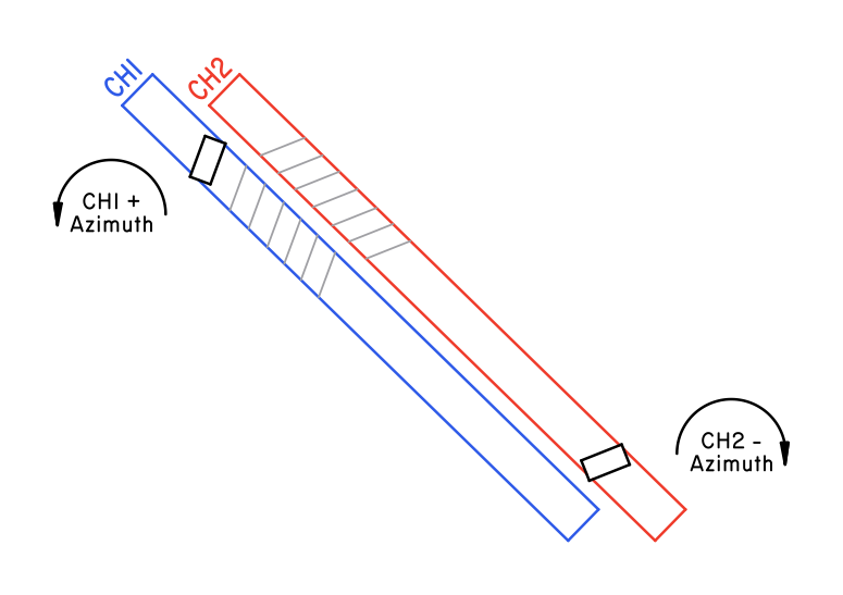
When azimuth is correctly adjusted, the signals read by CH1 and CH2 head are both strongest (nominal) when they read their corresponding CH1/CH2 video tracks. When azimuth is misadjusted, there is an additional attenuation - azimuth scanning loss.
Linear audio tracks also experience azimuth loss due to azimuth mis-adjustment of the A/C head. This is the exact same physics of the process as with the video heads, despite the major difference between the kind of signals they read!
Note: this is my best attempt at making an azimuth loss model, but it may still be lacking. I did not really have means to verify this model against real world data - so consider it to represent “idealistic” behavior rather than numerically real.
The azimuth scanning loss depends on the size of the head gap and the wavelength of the signal. To approximately estimate it, first the “smear offset” is calculated - an approximate distance between leading and trailing ends of the head gap as projected onto the signal: $$SmearOffset = TrackWidth \cdot sin(HeadAzimuthAngle)$$ When head has non-zero azimuth relative to the track, this results in leading and trailing ends of the head gap to shift from being aligned with the signal waveform (assumed to be a sine wave in this case) to being read across the smear offset worth of the signal waveform.
From this, azimuth loss can be estimated by the sinc function, the integral of the magnetic flux over across the head gap (which is defined by smear offset along the direction of signal) for a sine wave signal: $$X = \frac{\pi \cdot SmearOffset}{Wavelength}$$ $$AzimuthLoss = sinc(X) = \frac{sin(X)}{X}$$
This azimuth loss model is defined for a sine wave signal. For the linear audio track, this is simply the base wavelength of the sine wave. For video signal, the situation diverges: azimuth rejection on luma signal is steeply different from chroma signal.
The wavelength can be determined as such: $$Wavelength = WaveVelocity / Frequency$$
The nominal linear velocity of the video head over the VHS tape is 5.80 meters per second. The frequency is fixed for the sine signal and variable for the video signal.
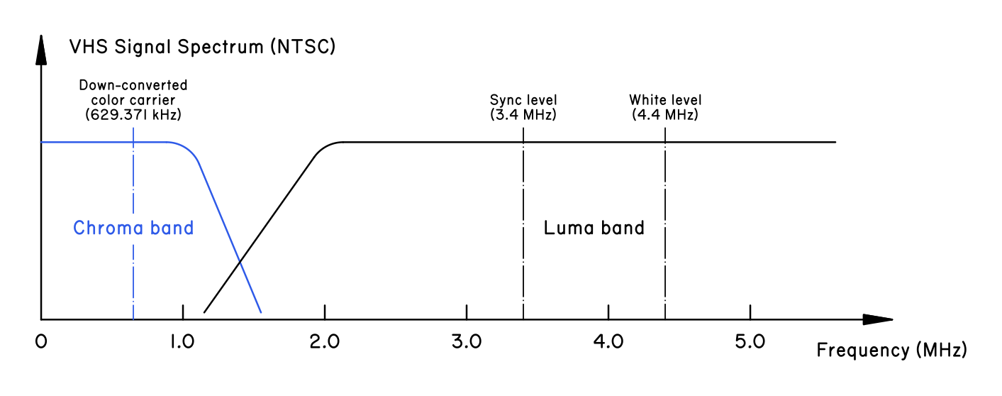
For luminance signal, the frequency is between 3.4 MHz and 4.4 MHz. For the chroma signal, due to down-conversion that is used with VHS, the frequency is centered around 0.629 MHz. There is also a considerable amount of energy in the side-lobes of the FM modulated carriers.
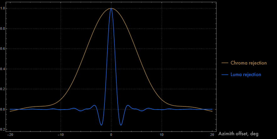
The wavelength is 9.2 um for chroma signal and ~1.5 um for luma signal (taking ~3.9 MHz as the reference frequency), which means a considerable difference in rejection between these two kinds of signal - chroma has very weak rejection while luminance signal has great rejection.
The graph below is obtained by integrating across many frequencies. The simulator shows the RF envelope using the luma recording wavelength - currently the actual simulator uses a simplified exponential fit to the center luma peak: $$AzimuthLoss \approx Exp(-0.75 \cdot HeadAzimuthAngle_{deg})] $$ This specific model represents the center of the luma rejection curve very well, but does not represent the sinc oscillating behavior at higher azimuth angles. So it’s valid in about 1.5° range.
Model Description - Full RF Envelope⌗
The actual plots and model outputs are calculated using the RF envelope model. There are two components to it: RFMagnitudeForHeadPosition and RFEnvelopeFull.
RFMagnitudeForHeadPosition function returns magnitude of RF signal for the specific video head located at a specific lateral offset. It calculates overlap between the video head and the video track, calculates azimuth scanning loss and then applies head-specific gain value.
The function performs summing over all video tracks and returns separately the waveform of the nominal track and the waveform of all tracks except the nominal.
RFEnvelopeFull currently implements a basic VCR model. Two video heads (SP or EP) are calculated. Two Hi-Fi heads are also calculated for the Hi-Fi track. The function calculates the RF signal magnitude across the entire range for which model is evaluated.
At this point, additional adjustments are applied. Drum position offset from the protrusion height is calculated and offset is applied to the effective contact position between the video head and the tape.
Heads which are protruding outward from the drum result in an earlier contact with the tape, while the heads which are sunken into the drum result in a later contact. The current simulator does not reflect signal magnitude loss due to increased distance between the tape and the head.
Next, tape wrap envelope is calculated based on 180° + some extra wrap-around. This envelope is applied to the calculated RF values, correctly applying the geometric limitations of the video head contact with the tape, as well as progressive loss of signal at the contact points.
RFEnvelopeFull returns signal magnitude referenced to the ideal value, with the protrusion offset, lateral offset, RFMagnitudeForHeadPosition and the tape wrap envelope all properly applied.
Model Description - A/C Head⌗
The model of the audio/control head allows to play around with misadjusted X-value, tilt, azimuth. Both linear audio and CTL pulses are simulated.
CTL pulses are rather simplistic, just basic pulses corresponding to magnetic flux at the edges of the square wave control pulse. The CTL pulses depend on speed and A/C head alignment, but they are intended to be primarily illustrative.
The linear audio signals involve generating the representation of the entire audio signal. Azimuth, X-value and tracking knob position all affect linear audio phase relative to video signal/Hi-Fi audio phase (both are connected - they are written by the same video drum, while linear audio is read by the A/C head).
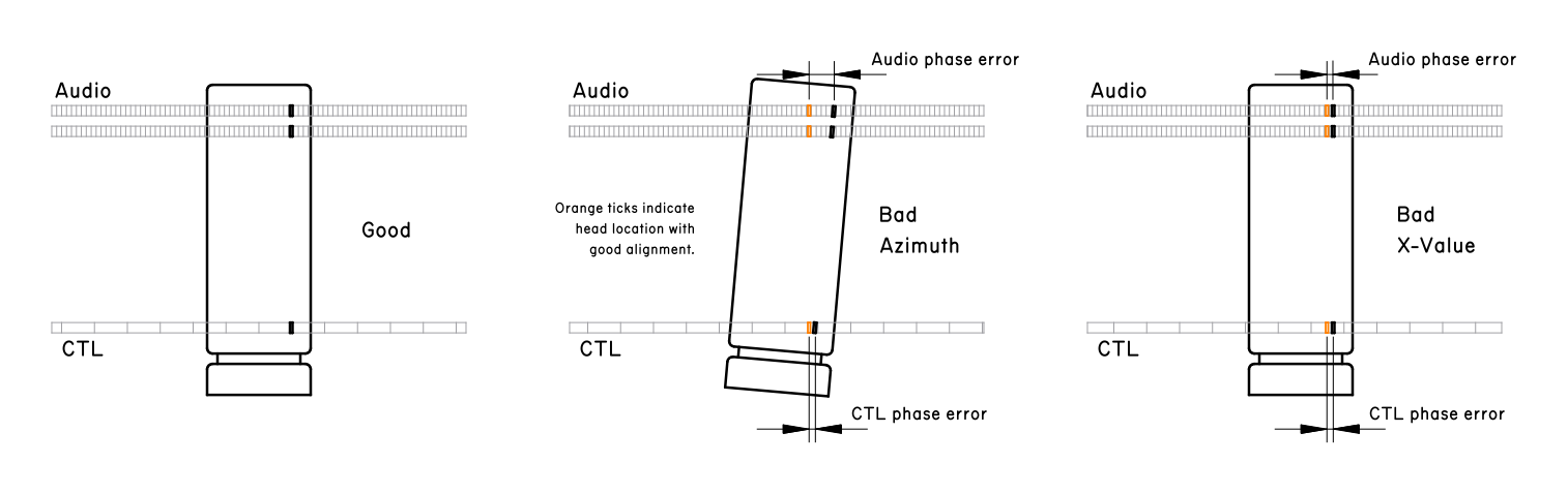
The A/C head model is mostly geometric:
- Azimuth loss is calculated based on geometric offset of heads from the correct track, based on the wavelength of the recorded waveform
- CTL head, linear audio R and linear audio L heads are separately calculated
- For each head, its geometric position due to tilt and azimuth of the A/C head is calculated
- A simplistic tilt attenuation model is applied to the signal (it is only illustrative - it tries to recreate what happens on the graphic when tilt parameter is adjusted)
- Phase offset is calculated. Due to geometric offset, all of the heads may read pulses/audio earlier or later. This has an effect on the behavior of the servo mechanism - azimuth adjustments to A/C head are equivalent to X-value adjustments
- For linear audio, response curve for the linear audio track (SP only for now) is applied
Model Description - Hi-Fi Locking⌗
This one is the simplest model of them all. If RF envelope of the Hi-Fi signal has dropouts below a certain threshold anywhere in the signal, the signal is considered to not lock.
This is based on the behavior of Hi-Fi lock on my BR-S800U: the lock is obtained if the signal was above threshold for a given time interval and is lost if there is any considerable drop-out happening.
Because the VHS simulator does not represent behavior of the system over longer timespan, it’s assumed that if the first two revolutions of the drum contain weak Hi-Fi signal, the lock is just unstable.