Sometime during the video club operations recently an anomaly was noticed: on VCR7 BR-S800U the ideal position for tracking was off-center. Actually, multiple commercial tapes exhibited better tracking meter values for adjusting the tracking knob about 1/3rd in tracking+ direction.
Because the A/C head alignment was known to be reasonably good but X-value was never adjusted before now, I assumed it is most likely an issue related to X-value. But to be entirely real - technically there exists a coupling between A/C head azimuth and X-value adjustment, because tilting of the head also tilts the CTL head and shifts the distance slightly, so these two adjustments cannot be fully separated from each other.
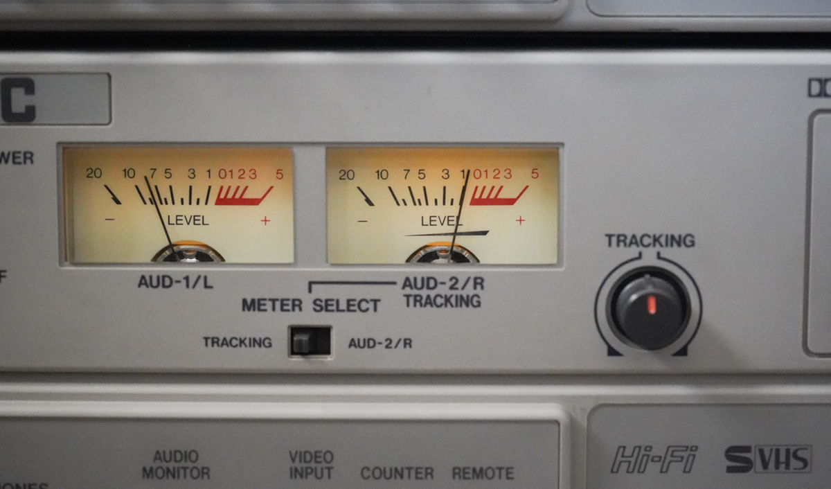
The picture above is just an illustration - previously this tracking level could only be attained by rotating the knob 1/3rd clockwise, while in this same neutral position the tracking meter would show -2..-3 dB or so.
Here’s the gist - for a well aligned VCR, the best tracking preset position should be somewhere around the center (meaning no alignment offset must be applied to play the tape at the maximum FM signal level). The system can be considered well-aligned if it satisfies the following checks:
- Phase difference between Hi-Fi and linear signal is very low (because phase of linear audio playback depends on X-value, when the audio/control head is well aligned the phase difference will be the lowest)
- Phase difference between linear track left & right is approaching zero (because azimuth of the audio/control head makes both tracks be aligned with the tape - no residual phase difference between them)
- The optimal tracking preset is in the center, while the shape of the tracking signal response for sweeping the entire tracking preset is largely symmetrical (e.g. Hi-Fi tracking loss occurs roughly at same positions of tracking offset)
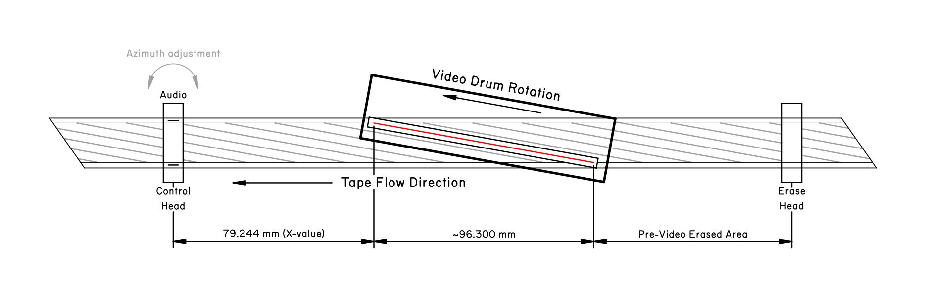
So there is an important element here - measuring relative phase offset. Previously I did this using a 7 kHz sine wave… which only lets me align things to precision of a single sine wave cycle at 7 kHz.
Which is 33.35 mm/s (NTSC tape speed) divided by 7000 Hz (reference frequency) - the length of a single sine wave cycle of linear audio at 7 kHz is approximately 4.8 micrometers.
Suddenly, an idea appears: because it’s not possible to tell phase offset (and therefore geometric offset) on a normal sine wave beyond 1 cycle (~4.8 micrometer) accuracy, what if I did amplitude modulation on the sine wave code to encode a higher-order phase correlation?
The idea is inspired by LTC timecode (encoded in linear audio tracks) and by the way laser rangefinders work (determining both fine and coarse components of phase offset). The result is a phase code:

The entire transmission of these codes is phase-aligned, e.g. each of these codes contains the same sine wave phase. The code then allows both fine and coarse measurement of phase:
- Coarse measurement in time window of up to about 1 second (33,500 micrometers worth of geometric distance) is possible by taking code transmissions and comparing their binary code as well as the timing of where the pilot begins
- Fine measurement in time window of up to 1 cycle (4.8 micrometers) is possible by comparing the phase of the sine wave in the pilot or anywhere across the code
This specific code is made to be very easy to sync and “catch” on the oscilloscopes - the pilot level is always greater than transmission levels, so it’s easy to catch it by simple level trigger.
Five bits of sequential code are simply a linearly incrementing Gray code (so each two nearby transmissions only differ by a single bit). The field number is initialized to the field number currently transmitted - I got the code to be properly synchronized with the video.
The same sequential code is transmitted twice - first for field 1, then for field 2. So the sequential code increments every NTSC frame, and it’s the field ID bit that distinguishes codes bound for one frame but from different fields.
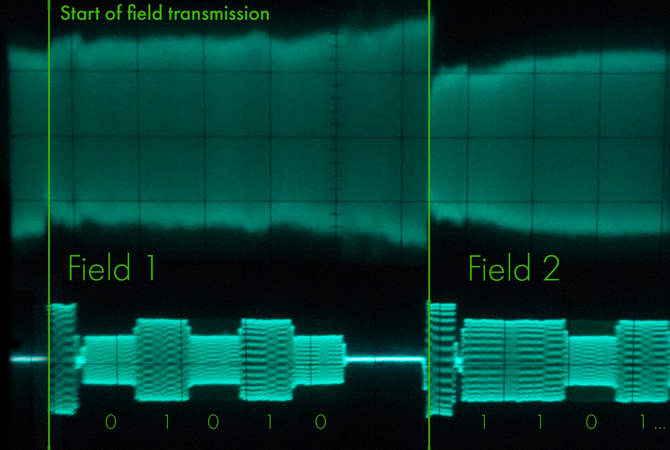
The code is also useful for absolute adjustment of audio phase relative to the video phase - my test generator is now programmed to output audio/video in such way that the beginning of the pilot exactly coincides with the start of transmission of the video frame. The entire code is one field long.
So now are the real oscilloscope traces from the VCR7. First, the initial state of phase difference between Hi-Fi and linear sound outputs revealed the real misalignment in X-value:
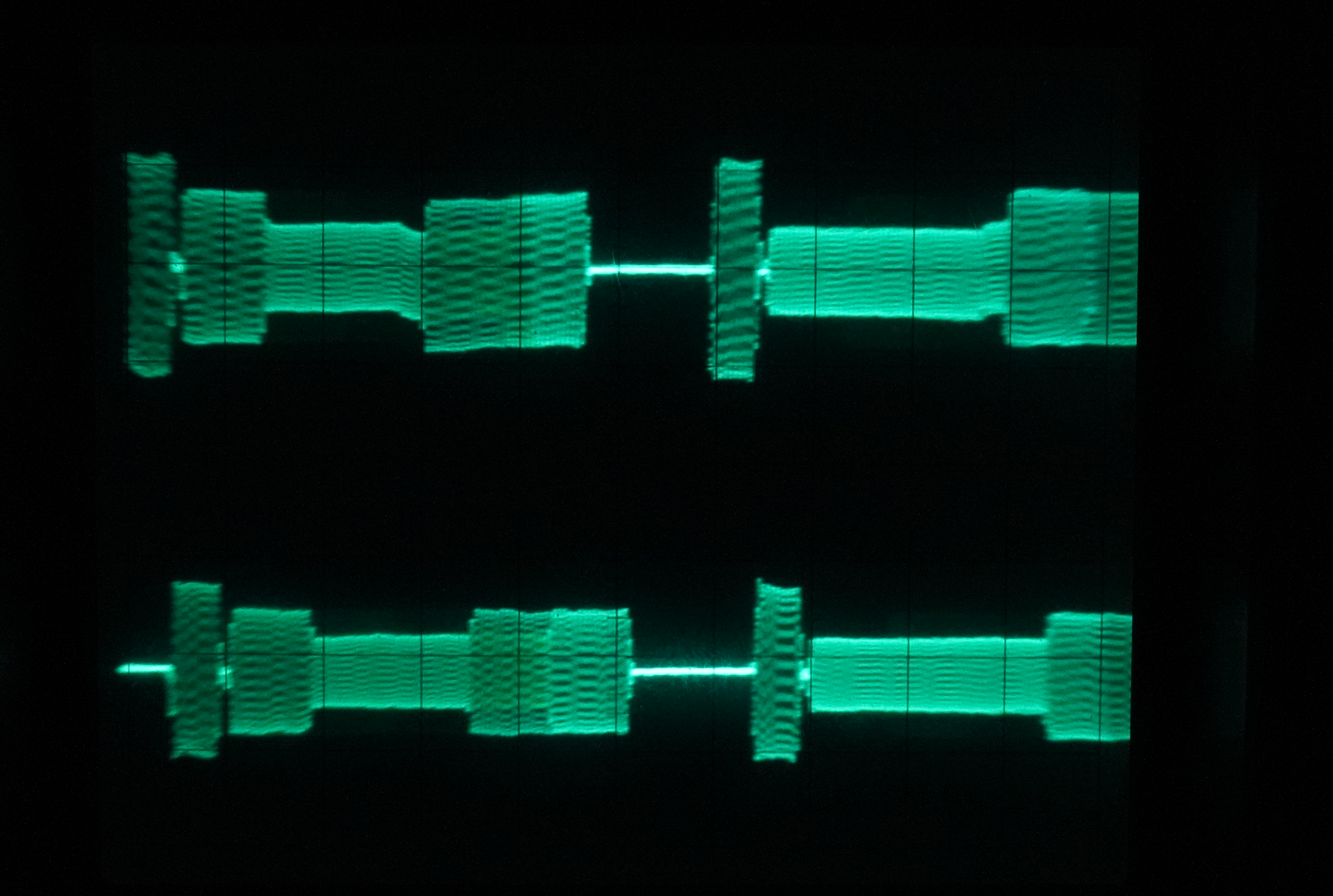
It makes sense - tilt of the A/C head and X-value are the only two variables previously not aligned on this VCR, with tilt being adjusted in the previous blog post.
Important note: the source tape with this signal was recorded on my well-aligned VCR. The methodology does not sit in simply nullifying the phase between Hi-Fi and linear audio since this requires a tape that was recorded on a well aligned deck.
So naive matching of the phase here results in only aligning one VCR to another VCR. The centroid methodology requires something beyond this - the signal becomes a reference and what’s hunted is not perfect match between Hi-Fi and linear audio phase but specific conditions under which the mechanical system falls into a local optimum/extrema. More on this in the next post…
But after performing the alignment in question, here is the final result:
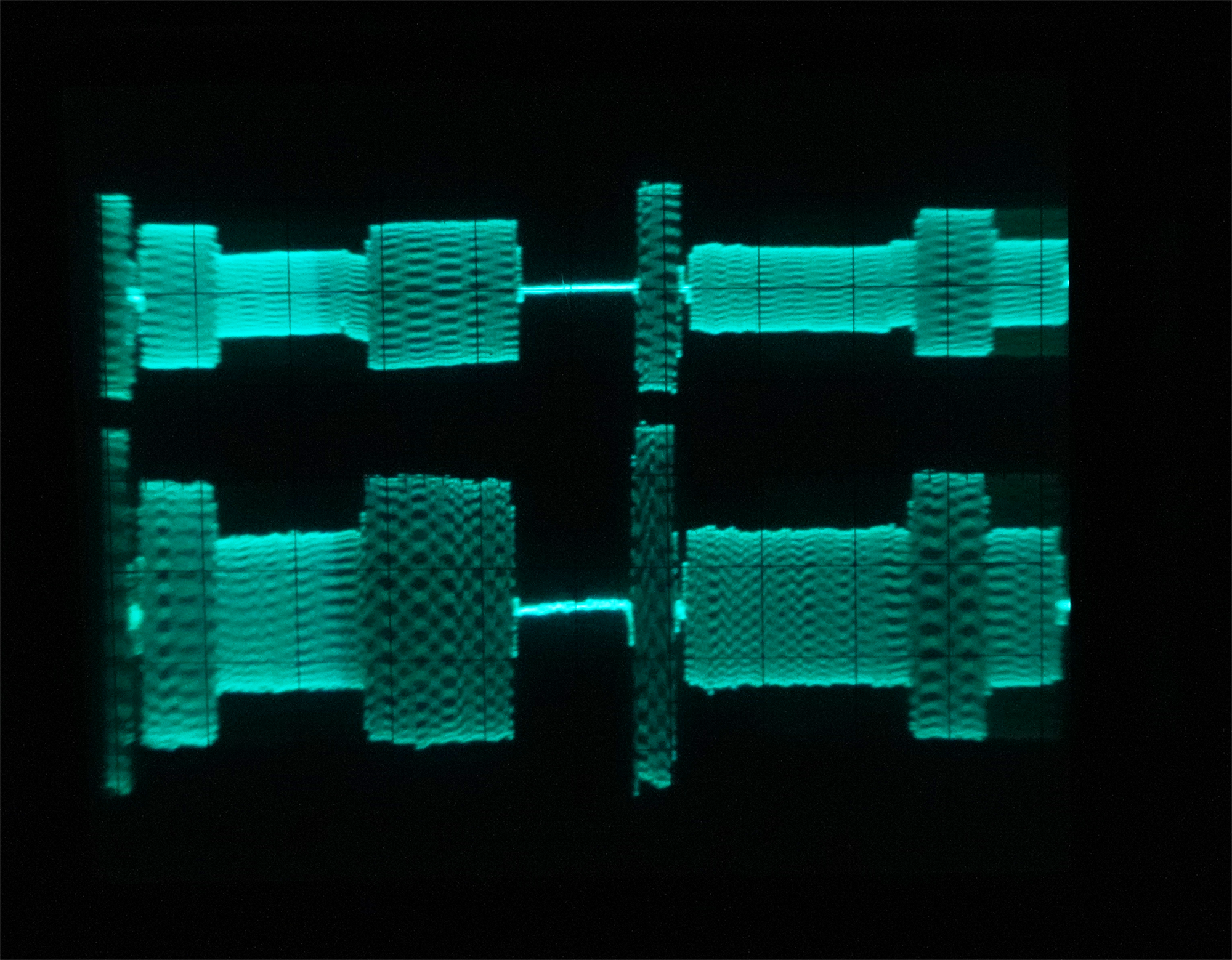
A considerable improvement! The signals are now basically in-phase. Some residual remains - that’s the result of the centroid alignment methodology overriding pure transfer of alignment from one deck to another.
The specific meaning of the residual phase offset is this: the optimal point at which the VCR7 appears to perform most mechanically aligned across the test set of tapes seems to be slightly different than the “factory ideal” alignment of VCR1. Both VCRs are now within some small residual of the optimal alignment - one because it was aligned at the factory and used very little since while being kept in good condition, other because it naturally settled into the correct alignment after centroid iterative methodology.
One last thing - I also checked ability to record field-synced signals to the tape in order to create better alignment records (essentially alignment tapes that are referenced to a specific VCR rather than the VHS standard). On the picture below you can see almost success:
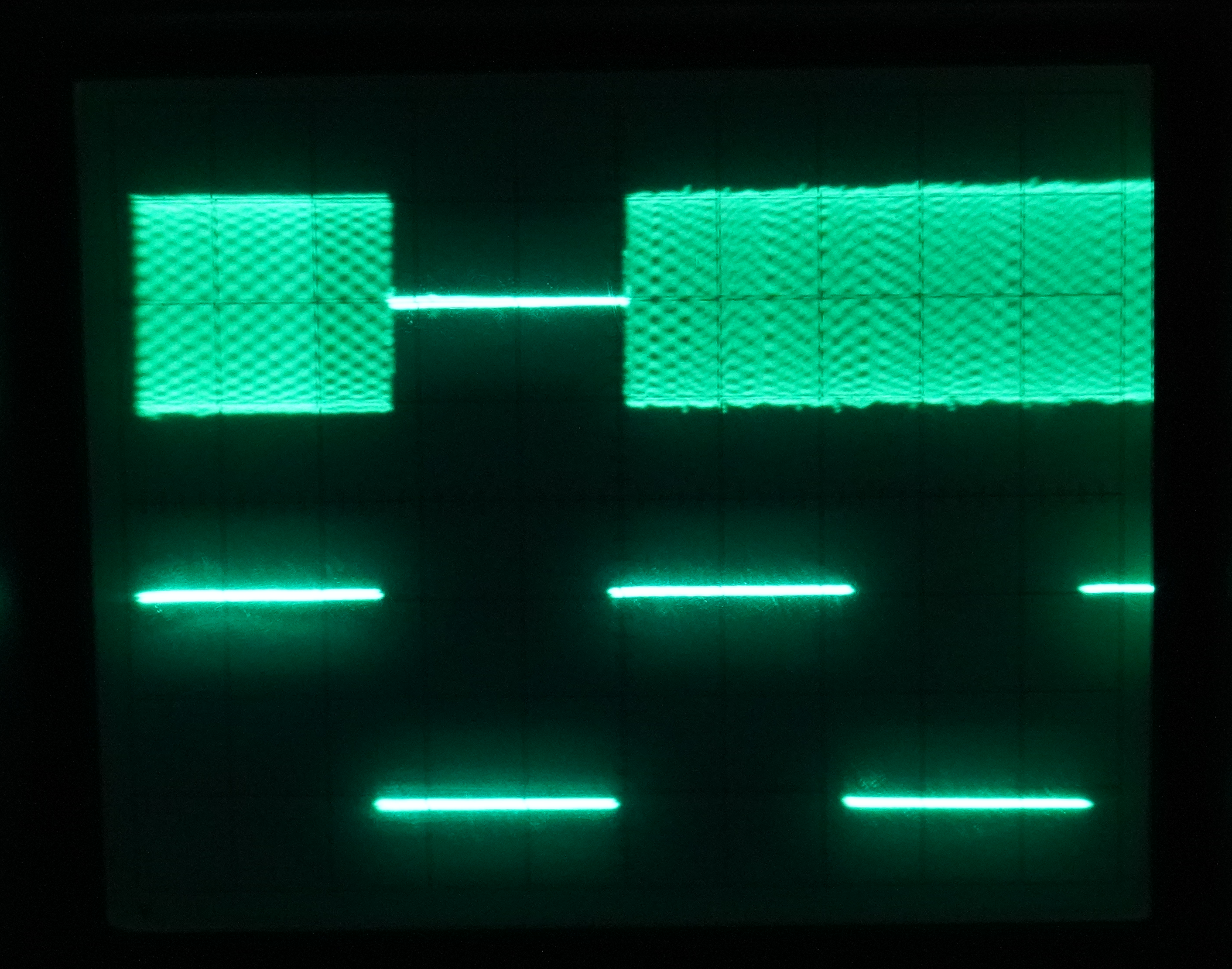
What’s missing here is pretty funny. The A/V data is stored as an mp4 file and then output by the BlackMagic Intensity Pro card with the supplied toolset (which is SO JANKY by the way).
The sound is accurately timed to frames and fields… except the mp4 files count video from the start of first image line. But analog signals have 21 lines of preamble - the vertical blanking interval together with vertical sync pulses, so the mp4 file must be encoded with this preamble duration baked in.
That’s something I ended up fixing later - works beautifully now, the output of the card contains both video and audio in correct sync (which can be verified independently and then from there it can become a source of calibrated signal for recording and using alignment record tapes).
Final thoughts on X-value adjustment⌗
The X-value adjustment nut on BR-S800U is kinda strange at first - it requires many rotations for small ultra-fine adjustments. The effect of azimuth adjustment tends to be considerably more impactful on the phase of linear audio, however even these slight ultra-fine adjustments of the taper nut seem to change how the tracking works.
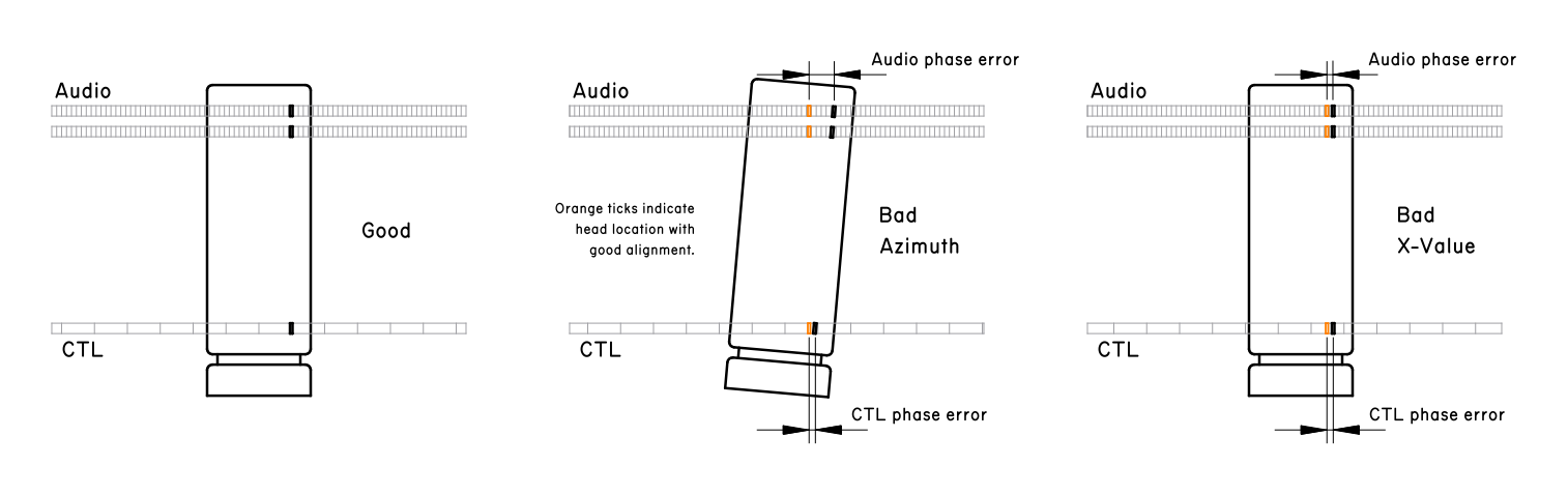
So I put together a graphic that explains somewhat why azimuth adjustment is coupled with X-value adjustment and why the magnitude of phase offset is magnified with audio tracks.
The final methodology was like this:
- Align X-value until tracking shows ideal behavior
- Adjust azimuth coarsely to bring linear in sync with Hi-Fi audio
- Vary X-value (without changing it - just shift it up, then shift down, then back to initial) - observing that tracking behavior still changes same way as before
- Adjust azimuth precisely to match waveform phase
- Vary tilt to see if it has any effect - it had no effect, wanted to confirm
- Final tracking sweep to check if everything is okay - if there is a residual offset anywhere, the procedure is repeated