VHS Playback Physics Simulator

I want to study my centroid methodology more conveniently and later prove formally that what I came up with actually results in aligned VCRs. So I have been working on a physics model of the VHS playback - specifically the impact of mechanical aspects of playback on the RF envelope read by video heads.

» The VHS playback simulator can be accessed here «

I’m not that good at HTML, so it’s just kludged together for the most part… but I think I fixed the most embarrassing HTML-related bugs by now.

This is effectively a purely geometric model with just basic physics - a very simple, idealistic reflection of what happens inside the VHS playback. The simulator calculates the following things:

  • How geometry of tape wraps around the drum
  • How the video heads pass over video tracks on the tape during rotation
  • The basic operation of the servo circuit and how CTL pulses are used
  • Simple model of the audio/control head that reflects how X-value, azimuth and tilt all impact the output signals
  • Simple model of linear and Hi-Fi audio which shows phase relationship between the two depending on the adjustments of the A/C head
  • Basic physics of azimuth rejection that ensure the signal from nearby tracks does not interfere with the track being currently read
  • Both EP and SP mode are supported, showing how much more sensitive the EP mode is to alignment (see this post 0014 for more information)

VHS Simulator Quick Reference

The VHS simulator will output the following indications, naming from top to bottom:

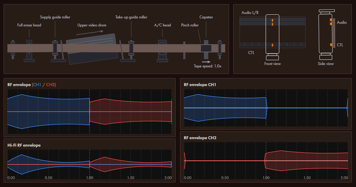
  1. Graphic indication of the tape transport path. A schematic indication illustrating the alignment of the tape to the video drum, position of the A/C head. All distances exaggerated
  2. Graphic indication of the A/C head alignment - azimuth, X-value offset, tilt
  3. RF envelope - predicted RF envelope as seen after the head amplifier of the VCR
  4. Hi-Fi RF envelope - predicted Hi-Fi RF envelope that accounts for narrower width of the Hi-Fi track
  5. Head switch pulse - shows signal that selects which head is connected to the amplifier. See also “head switch offset” parameter
  6. CTL pulses - simulation of the CTL pulses as read by the A/C head
  7. Relative audio phases - 10x zoomed in view of the Hi-Fi, linear audio left and linear audio right waveforms. This indicates the relative phase between all of these signals, which will vary with X-value adjustments and A/C head azimuth
  8. RF envelope CH1 - output of the CH1 video head, including the dead zone when it is not touching the tape
  9. RF envelope CH2 - same for CH2 video head
  10. Linear audio R - right channel of the linear audio track (shown at the same scale as the RF envelope)
  11. Linear audio L - left channel of the linear audio track
  12. Hi-Fi audio - audio picked up from the Hi-Fi system. The audio will vanish if Hi-Fi is predicted to not have been reliably established

Underneath there is a list of parameters for the model that can be edited and the tracking meter (I couldn’t really fit it anywhere else). The tracking level meter is made to work the same way as it does on my BR-S800U - it shows the integrated RF envelope.

This is a short reference for all the model parameters, see below for a more detailed explanation of the physics involved:

ParameterDescription
Playback modeSelects between SP or EP playback mode (EP tape runs at 1/3rd of the rate the SP does, the tracks are much more narrow and the EP video heads are accordingly adjusted)
Tape speedCurrent tape playback/shuttle speed. 1.0x means normal playback, 0.0x is still mode, -1.0x is reverse playback mode
Tracking knobTracking adjustment knob - allows adjusting tracking same way it works on my BR-S800U (offset by one SP track width - in EP mode it crosses over multiple tracks)
Supply offsetVertical offset of the supply side tape guide pole. Adjusts how the tape enters the video drum
Take-up offsetVertical offset of the take-up side tape guide pole. Adjusts how the tape leaves the video drum
X-value adjustmentOffset along the direction of tape flow of the A/C head position that defines phase relationship between CTL pulses and video track positions
Head switch offsetAllows adjusting where the VCR performs a head switch. It’s mostly just illustrative of the mechanic, it is usually supposed to be set to 0%
A/C head tiltSee A/C head graphic for visual illustration of the tilt angle. Affects how well the tape comes in contact with CTL head and linear audio R/L heads. Very simplistic modelling just for illustrative purposes
A/C head azimuthAzimuth of the A/C head. See graphic. Affects the phase relationship between CTL, linear audio R/L tracks.
A/C head heightVertical height adjustment of the A/C head that models the vertical misalignment between the A/C individual heads and the tracks on the tape
CH1/CH2 azimuth errorAzimuth deflection of the video head (see “azimuth scanning loss” chapter for more details)
CH1/CH2 gainAdditional gain in decibels for the specified head (no specific physics meaning - just allows adjusting amplification for both heads individually)
CH1/CH2 heightHeight/altitude offset of the video head. This is vertical offset along the drum rotation axis - maps to lateral offset between the head and the video track
CH1/CH2 protrusionDistance by which the video head sticks outside of the normal diameter of the video drum. This causes the heads to come in contact with tape earlier and leave contact later, additionally skewing the time base of the actual FM segment that ends up in the head switching window for that head. Negative values correspond to severe head wear, indicating that head has “receded” closer into the drum
Recorded signal typeWhich audio signal is recorded on the tape (stereo L/R tracks plus Hi-Fi). Allows to select sine wave or the pulse coded sine wave for absolute phase determination. The pulse coded (AM-modulated) sine wave will illustrate the phase offset in absolute terms where normal sine wave cannot.
Recorded signal frequencyBase frequency for the recorded signal. This affects azimuth scanning losses for the audio heads due to A/C head azimuth, the visual display of the signal and have some effect on the amplitude of the audio signal due to linear audio response curve (in current simulator the response curve is assumed for SP recording)

Model Description - Time Around Drum

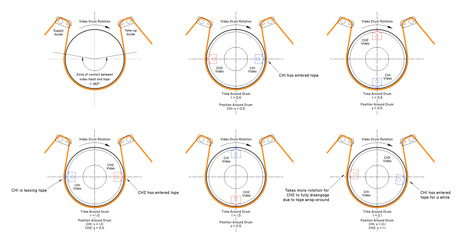
The main input variable of the entire model is time around the drum (TimeAroundDrum a.k.a. tau). It is a unitless measure of both time and space dependencies in the movement of the video drum:

  1. CH1 video head begins to touch tape at 0.0 tau - the supply-side contact point
  2. The video drum performs first half-rotation, scanning the first field
  3. The CH1 head leaves tape at 1.0 tau, CH2 head begins to contact tape at the same time. CH1 leaves at take-up side, the CH2 enters at supply side
  4. The CH2 head scans across the tape as drum performs second half-rotation, scanning the second field
  5. CH2 head leaves the tape at 2.0 tau

The explanation above is somewhat simplified - actually CH1 head begins to contact tape slightly earlier than 0.0 tau and stops contacting tape slightly later after 1.0 tau (because tape is wrapped by more than 180 degrees around the drum!). This slight overlap allows to establish a truly seamless switching between the two channels and create a continuous FM signal.

The range of 0.0 to 2.0 tau represents the full single rotation of the video drum. Because the system is mechanically coupled, during normal operation of the drum “time” and “angular position of the drum” mean the same thing.

The position around the drum (PositionAroundDrum) is almost the same value as TimeAroundDrum, but brought to a normalized range of -0.5..1.5 to represent exact geometric position of video head around the span of rotation and around the VHS tape itself.

Time around the drum is used as “time” input to the model (for drawing RF envelope and audio signals over time), with “position” being calculated from it for each of the video heads.

Model Description - Video Head Scan Model

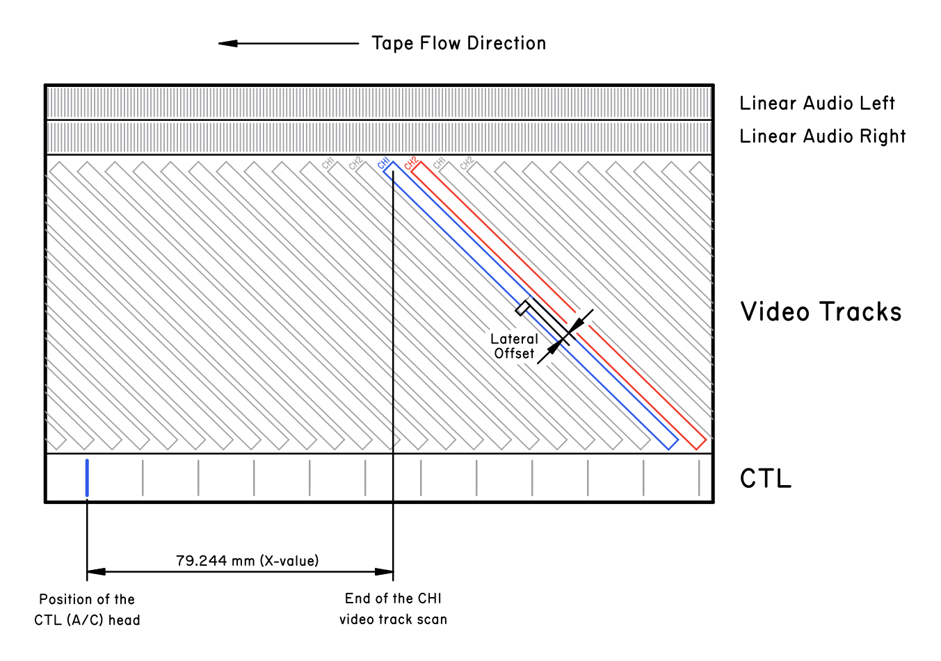
To calculate the RF envelope a very simple geometric model is used. Based on a variety of the parameters, the lateral offset between the video reading head and the video track is determined.

The lateral offset is measured perpendicular to the video track, effectively it is the deviation between the video head and the nominal video track (the video track that the video head would read in properly aligned conditions).

The lateral offset is used to determine how much of the video head actually overlaps with the video track. The signal attenuation due to misalignment is taken proportional to the amount of overlap between the video head and the video track.

The lateral offset is a sum of the following factors:

OffsetFormulaDescription
Supply Guide Lateral OffsetGuideSupplyOffset * exp(-s/const)Lateral offset due to supply guide adjustment, with mechanical relaxation across the drum span.
Take-up Guide Lateral OffsetGuideTakeupOffset * exp(-(1-s)/const)Lateral offset due to take-up guide adjustment, with mechanical relaxation across the drum span.
Bow OffsetBow * s * (1 - s)Parabolic bow due to stretching/elastic response of the VHS tape as it is wrapped around the drum. Strongest at equidistance between two tape guides.
Tracking Phase OffsetTrackingAdjustment * SP_TrackPitchTracking adjustment offsets the relative phase between CTL pulses and video tracks, resulting in a simple lateral offset.
Tape Flow Drift(Speed - 1.0) * TrackPitch * TauWhen tape is played back at 1.0x rate, the movement of the tape is aligned with movement of the video head, resulting in no lateral drift. But at any other speeds drift appears.
CTL Phase OffsetThetaSin * CTL_LateralOffsetA/C head azimuth and X-value adjustment both shift the CTL head along the tape length. This offset accounts for that, converting the lateral offset along the tape into lateral offset perpendicular to the video track.
Altitude OffsetHeadAltitudeHead altitude is the height adjustment of the video drum head. Because the rotation of video heads is aligned with video tracks, any height offset of the video heads becomes simple lateral offset between head and the video track.

There is an additional factor that modifies the effective position of the head around the drum, but it’s implemented at the level of the RF envelope model (see below). Protrusion of the video heads (due to wear or mechanical misadjustment) will cause the heads to come in contact with the tape earlier or later than intended.

Model Description - Azimuth Scanning Loss

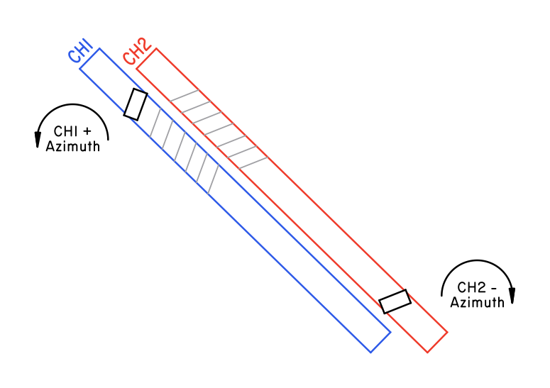
The two video heads in the VHS system are slightly rotated relative to each other in a way that I can only best illustrate using the picture below. The two heads have a +6° and a -6° azimuth - and the video tracks are actually laid down “skewed” accordingly.

This mechanism implements azimuth rejection: CH1 head will “see” a considerably reduced signal intensity of CH2 tracks, while CH2 will not “see” the CH1 video tracks.

When azimuth is correctly adjusted, the signals read by CH1 and CH2 head are both strongest (nominal) when they read their corresponding CH1/CH2 video tracks. When azimuth is misadjusted, there is an additional attenuation - azimuth scanning loss.

Linear audio tracks also experience azimuth loss due to azimuth mis-adjustment of the A/C head. This is the exact same physics of the process as with the video heads, despite the major difference between the kind of signals they read!

Note: this is my best attempt at making an azimuth loss model, but it may still be lacking. I did not really have means to verify this model against real world data - so consider it to represent “idealistic” behavior rather than numerically real.

The azimuth scanning loss depends on the size of the head gap and the wavelength of the signal. To approximately estimate it, first the “smear offset” is calculated - an approximate distance between leading and trailing ends of the head gap as projected onto the signal: $$SmearOffset = TrackWidth \cdot sin(HeadAzimuthAngle)$$ When head has non-zero azimuth relative to the track, this results in leading and trailing ends of the head gap to shift from being aligned with the signal waveform (assumed to be a sine wave in this case) to being read across the smear offset worth of the signal waveform.

From this, azimuth loss can be estimated by the sinc function, the integral of the magnetic flux over across the head gap (which is defined by smear offset along the direction of signal) for a sine wave signal: $$X = \frac{\pi \cdot SmearOffset}{Wavelength}$$ $$AzimuthLoss = sinc(X) = \frac{sin(X)}{X}$$

This azimuth loss model is defined for a sine wave signal. For the linear audio track, this is simply the base wavelength of the sine wave. For video signal, the situation diverges: azimuth rejection on luma signal is steeply different from chroma signal.

The wavelength can be determined as such: $$Wavelength = WaveVelocity / Frequency$$

The nominal linear velocity of the video head over the VHS tape is 5.80 meters per second. The frequency is fixed for the sine signal and variable for the video signal.

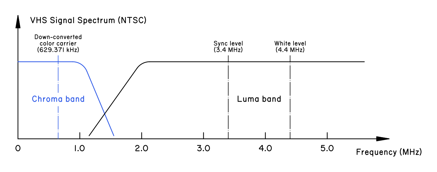
For luminance signal, the frequency is between 3.4 MHz and 4.4 MHz. For the chroma signal, due to down-conversion that is used with VHS, the frequency is centered around 0.629 MHz. There is also a considerable amount of energy in the side-lobes of the FM modulated carriers.

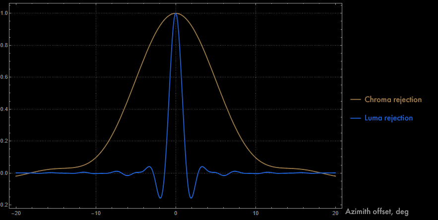
The wavelength is 9.2 um for chroma signal and ~1.5 um for luma signal (taking ~3.9 MHz as the reference frequency), which means a considerable difference in rejection between these two kinds of signal - chroma has very weak rejection while luminance signal has great rejection.

The graph below is obtained by integrating across many frequencies. The simulator shows the RF envelope using the luma recording wavelength - currently the actual simulator uses a simplified exponential fit to the center luma peak: $$AzimuthLoss \approx Exp(-0.75 \cdot HeadAzimuthAngle_{deg})] $$ This specific model represents the center of the luma rejection curve very well, but does not represent the sinc oscillating behavior at higher azimuth angles. So it’s valid in about 1.5° range.

Model Description - Full RF Envelope

The actual plots and model outputs are calculated using the RF envelope model. There are two components to it: RFMagnitudeForHeadPosition and RFEnvelopeFull.

RFMagnitudeForHeadPosition function returns magnitude of RF signal for the specific video head located at a specific lateral offset. It calculates overlap between the video head and the video track, calculates azimuth scanning loss and then applies head-specific gain value.

The function performs summing over all video tracks and returns separately the waveform of the nominal track and the waveform of all tracks except the nominal.

RFEnvelopeFull currently implements a basic VCR model. Two video heads (SP or EP) are calculated. Two Hi-Fi heads are also calculated for the Hi-Fi track. The function calculates the RF signal magnitude across the entire range for which model is evaluated.

At this point, additional adjustments are applied. Drum position offset from the protrusion height is calculated and offset is applied to the effective contact position between the video head and the tape.

Heads which are protruding outward from the drum result in an earlier contact with the tape, while the heads which are sunken into the drum result in a later contact. The current simulator does not reflect signal magnitude loss due to increased distance between the tape and the head.

Next, tape wrap envelope is calculated based on 180° + some extra wrap-around. This envelope is applied to the calculated RF values, correctly applying the geometric limitations of the video head contact with the tape, as well as progressive loss of signal at the contact points.

RFEnvelopeFull returns signal magnitude referenced to the ideal value, with the protrusion offset, lateral offset, RFMagnitudeForHeadPosition and the tape wrap envelope all properly applied.

Model Description - A/C Head

The model of the audio/control head allows to play around with misadjusted X-value, tilt, azimuth. Both linear audio and CTL pulses are simulated.

CTL pulses are rather simplistic, just basic pulses corresponding to magnetic flux at the edges of the square wave control pulse. The CTL pulses depend on speed and A/C head alignment, but they are intended to be primarily illustrative.

The linear audio signals involve generating the representation of the entire audio signal. Azimuth, X-value and tracking knob position all affect linear audio phase relative to video signal/Hi-Fi audio phase (both are connected - they are written by the same video drum, while linear audio is read by the A/C head).

The A/C head model is mostly geometric:

  • Azimuth loss is calculated based on geometric offset of heads from the correct track, based on the wavelength of the recorded waveform
  • CTL head, linear audio R and linear audio L heads are separately calculated
  • For each head, its geometric position due to tilt and azimuth of the A/C head is calculated
  • A simplistic tilt attenuation model is applied to the signal (it is only illustrative - it tries to recreate what happens on the graphic when tilt parameter is adjusted)
  • Phase offset is calculated. Due to geometric offset, all of the heads may read pulses/audio earlier or later. This has an effect on the behavior of the servo mechanism - azimuth adjustments to A/C head are equivalent to X-value adjustments
  • For linear audio, response curve for the linear audio track (SP only for now) is applied

Model Description - Hi-Fi Locking

This one is the simplest model of them all. If RF envelope of the Hi-Fi signal has dropouts below a certain threshold anywhere in the signal, the signal is considered to not lock.

This is based on the behavior of Hi-Fi lock on my BR-S800U: the lock is obtained if the signal was above threshold for a given time interval and is lost if there is any considerable drop-out happening.

Because the VHS simulator does not represent behavior of the system over longer timespan, it’s assumed that if the first two revolutions of the drum contain weak Hi-Fi signal, the lock is just unstable.

Anomaly in CEA-608 Subtitles

I found a CEA-608 encoding anomaly on the Little Shop of Horrors VHS (catalog no. 11702). At some point during the showing there is a subtitle encoded as “CANAPé” instead of “CANAPÉ” as following the style would call for.

The usual style for captions is all-uppercase letters for dialog, normal case letters for whispering. A later extension (CEA-608-B) added extended italic tags… but I’ve never seen them used in a movie just yet.

Why does this anomaly exist: the base CEA-608 character set only includes a lowercase “é” encoded as part of the basic set (single byte 0x5C). Uppercase “É” was only added later and is part of the extended character set 1.

So either this was encoded before the CEA-608-B extension or more likely it was just encoded on legacy hardware/through a legacy working process. The uppercase “É” would be encoded by three bytes: 0x45 0x12 0x21, which will print basic character set “E” followed by a control code which - if supported - will step one character back and overwrite “E” with “É”.

The CEA-608 standard says “transmit the standard character that most closely resembles the extended character, for receivers that can’t decode it”… so there is a way to encode this in a better way - if the closed captions encoding system used would allow to enter such a sequence.

This would be the CEA-608 sequence for the subtitle in question: 0x4341 0x4E41 0x505C 0x1221 (grouped by two bytes). What it encodes: “CANAPé” followed by “extended set 1 character É” command which implicitly performs a backspace.

This would output “CANAPÉ” on later decoders and revert to “CANAPé” on earlier decoders without a violation of the spec in spirit (usually E is considered the fallback character for all E-accented character glyphs).

Philosophy of VCR Alignment

Attention: this is not yet working methodology, just my drafts of what I am considering of including in the final document. While I am working on writing the centroid methodology document, I will be publishing draft sections of what I am working on.

The text is intended to be followed by technical illustrations and pictures - these will be in the final document, but are not going to be included in the drafts.


What is good alignment?

In my personal opinion based on operating a video club where we routinely watch magnetic media, a tape system can be considered well-aligned when it satisfies the following practical points:

  1. Good playback of audio and video - good sync, good image quality, no fuzzies, zero tracking setting usually is the sweet spot for most tapes
  2. Tape flows smoothly through the transport and doesn’t crease/get caught/get damaged by anything
  3. For recording systems only: recorded audio and video signals play on other machines with no tracking adjustments

Most VCRs will play video just fine and will not damage the tape in their default state. You generally do not need to perform alignment in the first place as normal wear the VCRs experience still does not take the machinery too far out of the normal alignment.

However if you are rebuilding the machine and swapping key components around, the re-alignment becomes mandatory to get the machine to play anything. Therefore it seems fair to say that alignment is not a thing you do to improve the quality of playback but instead a technical operation you execute when you need to re-calibrate the VCR for a known good reason.

So the golden rule is don’t touch it if it works. Good alignment is when the player will reproduce the tapes. I had to re-align my player because it would not reproduce any tapes at all (the image came out corrupted since parts from different VCRs differed in exact geometry and adjustments).

Another thing worth mentioning: there exists a nominal alignment for the VHS system to which all VCRs were calibrated during the era when they were still around. These days all equipment you find will generally have experienced a degree of wear or simply has aged.

This gives a rise to the philosophical question of what is better - making the VCR aligned to the nominal specifications of the VHS system or making the VCR aligned to effective good playback of the tapes in modern times?

What is correct alignment?

If today was not the present day, the correct way to align a VCR would be the procedures described in detail in the service manual. These procedures require use of VCR-specific jigs and special alignment tapes which will encode correct signal that embeds inside of it geometric relationships so important to the configuration of the tape transport.

This is the first kind of correctness: normative correctness. A normative-correct alignment is the one made according to the original factory references. Such an alignment embeds exactly the key geometric values of the VHS system and brings VCR to agreement with the specification as it was printed.

Normative correctness was the correctness when the VHS format was not obsolete: the most assured way to record media that will be universally playable by assorted VCR machines was to calibrate the recording machine to normative correctness.

Normative correctness is the ideal. But factory alignment tapes and jigs are essentially unobtanium at this point. If you are very limited on resources like me, this path is impossible/too expensive/requires a prohibitive amount of effort.

However there is a second kind of correctness: effective correctness. An effective-correct alignment is the one that actually succeeds in playing back a broad sampling of VHS tapes, both commercial and home video. Effectively correct alignment has such key geometric values that they are in good coordination with the VHS standard and they result in accurate playback by the contemporary as-is device.

Effective correctness is what this methodology is aiming to attain. Not normative correctness. A VCR aligned according to the methodology presented here will be good at playing back tapes and will satisfy the requirements of “aligned well”… but it will not be a factory aligned VCR.

But today is the present and it has been many years since the VHS format became obsolete. Here is my opinion: effective correctness at this point is equivalent to normative correctness, but they are not the same thing.

In modern times, you can push VCR slightly further if you aim for effective correctness over normative, since the very parts VCR is made from are no longer very normative.

Philosophy and engineering of the dynamic systems

A well engineered, practical dynamic system (any machine, piece of software, any abstract design) generally exploits dynamic stability in some fashion.

If there is something dynamically unstable the engineering design calls to stabilize it. And now if something is dynamically stable (inherently so or because of a control system) then it will have a specific relation to dynamic state - be at some local extrema in the state space.

All of engineering effectively has to do with local optimization. The result is that engineered systems generally work in states which are locally optimized.

Here is how this connects to physical reality of VHS:

  1. The video heads must trace exact paths over the video tracks on the VHS cassette. Here is the local extrema: the resulting RF signal is at its highest when video head is aligned with the track, anything less than good alignment results in reduction of RF signal
  2. The control (CTL) pulses must arrive at the exact time the video head begins/finishes the traversal of the video track. Here is the local extrema: any deviation in pulse timing will offset the video heads off the correct tracks, the only correct alignment is the one which maximizes playback RF
  3. Two video heads must traverse the tape symmetrically and identically. There is nothing different about them - both heads read signal identically and are functionally interchangeable. The system is symmetrical, completely. Here is the local extrema: any deviation of one head from another changes the RF signal reading. The resulting playback is at its optimal when both heads behave symmetrically. If there was any residual azimuth or offset between the video track and video head, we will immediately see asymmetry in that one specific video head
  4. Capstan must pull the tape at the exact rate corresponding to video tracks and CTL pulses. Here is the local extrema: if pull speed is less than required or if pull speed is higher than required, then there is a constant shifting offset between the video heads and video tracks. This results in loss of stable RF and instead we get long-duration pulses (whenever heads ‘slide off’ the video track and show us the space between video tracks)
  5. Hi-Fi signal should be largely close and almost in-phase with linear audio signal. Here is the local extrema: these signals are synchronized during the recording, so any time offset during playback suggests that the geometric distance between the video drum (Hi-Fi audio) and the A/C head (linear audio) is incorrect.

So here is the fundamental statement on which this methodology is based on: VHS system in its aligned state sits at the local extrema by some key measurable parameters.

Therefore we can perform a alignment of a VCR by iteratively pushing it towards the local extrema using the commercial video tapes as a reference.

So what do I do?

In order to effectively repair a VCR you must understand the physics behind how everything works. How the servo system works, how the video head reads data off the tape, etc…

Explaining this is beyond the scope of the current document. That is the knowledge that should be obtained in parallel with this if you really do attempt something like this.

Phase Code for Accurate VCR Alignment

Sometime during the video club operations recently an anomaly was noticed: on VCR7 BR-S800U the ideal position for tracking was off-center. Actually, multiple commercial tapes exhibited better tracking meter values for adjusting the tracking knob about 1/3rd in tracking+ direction.

Because the A/C head alignment was known to be reasonably good but X-value was never adjusted before now, I assumed it is most likely an issue related to X-value. But to be entirely real - technically there exists a coupling between A/C head azimuth and X-value adjustment, because tilting of the head also tilts the CTL head and shifts the distance slightly, so these two adjustments cannot be fully separated from each other.

The picture above is just an illustration - previously this tracking level could only be attained by rotating the knob 1/3rd clockwise, while in this same neutral position the tracking meter would show -2..-3 dB or so.

Here’s the gist - for a well aligned VCR, the best tracking preset position should be somewhere around the center (meaning no alignment offset must be applied to play the tape at the maximum FM signal level). The system can be considered well-aligned if it satisfies the following checks:

  1. Phase difference between Hi-Fi and linear signal is very low (because phase of linear audio playback depends on X-value, when the audio/control head is well aligned the phase difference will be the lowest)
  2. Phase difference between linear track left & right is approaching zero (because azimuth of the audio/control head makes both tracks be aligned with the tape - no residual phase difference between them)
  3. The optimal tracking preset is in the center, while the shape of the tracking signal response for sweeping the entire tracking preset is largely symmetrical (e.g. Hi-Fi tracking loss occurs roughly at same positions of tracking offset)

So there is an important element here - measuring relative phase offset. Previously I did this using a 7 kHz sine wave… which only lets me align things to precision of a single sine wave cycle at 7 kHz.

Which is 33.35 mm/s (NTSC tape speed) divided by 7000 Hz (reference frequency) - the length of a single sine wave cycle of linear audio at 7 kHz is approximately 4.8 micrometers.

Suddenly, an idea appears: because it’s not possible to tell phase offset (and therefore geometric offset) on a normal sine wave beyond 1 cycle (~4.8 micrometer) accuracy, what if I did amplitude modulation on the sine wave code to encode a higher-order phase correlation?

The idea is inspired by LTC timecode (encoded in linear audio tracks) and by the way laser rangefinders work (determining both fine and coarse components of phase offset). The result is a phase code:

The entire transmission of these codes is phase-aligned, e.g. each of these codes contains the same sine wave phase. The code then allows both fine and coarse measurement of phase:

  1. Coarse measurement in time window of up to about 1 second (33,500 micrometers worth of geometric distance) is possible by taking code transmissions and comparing their binary code as well as the timing of where the pilot begins
  2. Fine measurement in time window of up to 1 cycle (4.8 micrometers) is possible by comparing the phase of the sine wave in the pilot or anywhere across the code

This specific code is made to be very easy to sync and “catch” on the oscilloscopes - the pilot level is always greater than transmission levels, so it’s easy to catch it by simple level trigger.

Five bits of sequential code are simply a linearly incrementing Gray code (so each two nearby transmissions only differ by a single bit). The field number is initialized to the field number currently transmitted - I got the code to be properly synchronized with the video.

The same sequential code is transmitted twice - first for field 1, then for field 2. So the sequential code increments every NTSC frame, and it’s the field ID bit that distinguishes codes bound for one frame but from different fields.

The code is also useful for absolute adjustment of audio phase relative to the video phase - my test generator is now programmed to output audio/video in such way that the beginning of the pilot exactly coincides with the start of transmission of the video frame. The entire code is one field long.

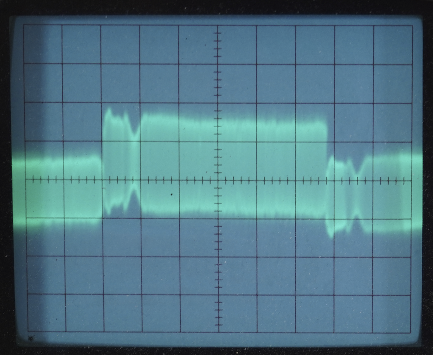
So now are the real oscilloscope traces from the VCR7. First, the initial state of phase difference between Hi-Fi and linear sound outputs revealed the real misalignment in X-value:

It makes sense - tilt of the A/C head and X-value are the only two variables previously not aligned on this VCR, with tilt being adjusted in the previous blog post.

Important note: the source tape with this signal was recorded on my well-aligned VCR. The methodology does not sit in simply nullifying the phase between Hi-Fi and linear audio since this requires a tape that was recorded on a well aligned deck.

So naive matching of the phase here results in only aligning one VCR to another VCR. The centroid methodology requires something beyond this - the signal becomes a reference and what’s hunted is not perfect match between Hi-Fi and linear audio phase but specific conditions under which the mechanical system falls into a local optimum/extrema. More on this in the next post…

But after performing the alignment in question, here is the final result:

A considerable improvement! The signals are now basically in-phase. Some residual remains - that’s the result of the centroid alignment methodology overriding pure transfer of alignment from one deck to another.

The specific meaning of the residual phase offset is this: the optimal point at which the VCR7 appears to perform most mechanically aligned across the test set of tapes seems to be slightly different than the “factory ideal” alignment of VCR1. Both VCRs are now within some small residual of the optimal alignment - one because it was aligned at the factory and used very little since while being kept in good condition, other because it naturally settled into the correct alignment after centroid iterative methodology.

One last thing - I also checked ability to record field-synced signals to the tape in order to create better alignment records (essentially alignment tapes that are referenced to a specific VCR rather than the VHS standard). On the picture below you can see almost success:

What’s missing here is pretty funny. The A/V data is stored as an mp4 file and then output by the BlackMagic Intensity Pro card with the supplied toolset (which is SO JANKY by the way).

The sound is accurately timed to frames and fields… except the mp4 files count video from the start of first image line. But analog signals have 21 lines of preamble - the vertical blanking interval together with vertical sync pulses, so the mp4 file must be encoded with this preamble duration baked in.

That’s something I ended up fixing later - works beautifully now, the output of the card contains both video and audio in correct sync (which can be verified independently and then from there it can become a source of calibrated signal for recording and using alignment record tapes).

Final thoughts on X-value adjustment

The X-value adjustment nut on BR-S800U is kinda strange at first - it requires many rotations for small ultra-fine adjustments. The effect of azimuth adjustment tends to be considerably more impactful on the phase of linear audio, however even these slight ultra-fine adjustments of the taper nut seem to change how the tracking works.

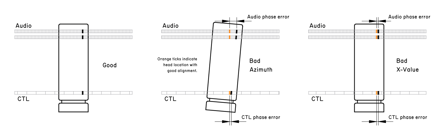
So I put together a graphic that explains somewhat why azimuth adjustment is coupled with X-value adjustment and why the magnitude of phase offset is magnified with audio tracks.

The final methodology was like this:

  1. Align X-value until tracking shows ideal behavior
  2. Adjust azimuth coarsely to bring linear in sync with Hi-Fi audio
  3. Vary X-value (without changing it - just shift it up, then shift down, then back to initial) - observing that tracking behavior still changes same way as before
  4. Adjust azimuth precisely to match waveform phase
  5. Vary tilt to see if it has any effect - it had no effect, wanted to confirm
  6. Final tracking sweep to check if everything is okay - if there is a residual offset anywhere, the procedure is repeated

Debugging CTL Issue for BR-S800U

Today I will be showing Tank Girl at the video machine… but yesterday during testing the tape exhibited a particular kind of a fault:

  • CTL counter is not advancing (which means the servo system is not sensing CTL pulses)
  • The image is unstable (it works fine for a bit, but then snow covers the screen for a moment)
  • Tracking meter is unstable (wobbly and unsteady suggesting that FM envelope is very bad)

The image being unstable is the consequence of servo system not having CTL signals as the input - the system does not know where video tracks begin and end actually, so as the playback continues the video head paths keeps drifting at a slight offset relative to the video tracks on the tape, periodically falling into the space between the tracks where there is no video data.

My initial hypothesis is related to one item I have not adjusted back when performing re-alignment of this rebuilt VCR: the tilt of the audio/control head.

In the VHS system, the A/C head reads linear audio (a form of low quality audio recorded along the length of the tape - unlike Hi-Fi which is mixed with video data) and it reads the control track - which stores pulses indicating exactly where each video track begins.

If this control track cannot be read, the servo system will not be able to synchronize properly to the video tracks on the tape and will result in the sort of symptoms that I got.

This head can be rotated in various axes in order to better conform to the flow of the tape. My initial adjustment set tilt only very coarsely and has not updated it since - so decided to perform the fine adjustment on top and see if that recovers playback of the problematic tape (spoilers: it did).

The tilt of the A/C head on the JVC BR-S800U is adjusted by four screws/bolts:

  • ① Forward tilt - the adjustment most relevant here
  • ② Azimuth adjustment - side-to-side lean relative to the tape (rotation on axis perpendicular to the plane of the tape)
  • ③ Height adjustment - shifts the A/C head up and down
  • ④ Taper nut for X-value adjustment - longitudinal position of the A/C head, only relevant for fine-tuning audio-video sync/the coarse component of the distance between the video drum and the A/C head

So… I went and did it. This was the methodology I came up with the day prior for this specific situation and this specific JVC BR-S800U:

  1. First check tape transport for any visible issues (make sure of the initial state of the alignment). Tape flow checks are implicit after each of the next steps
  2. Connect oscilloscope to linear audio R output and to CTL pulses, synchronize it on CTL pulses
  3. Record voltage magnitude of the CTL pulses and linear audio R output in the initial condition.
  4. Adjust forward tilt ① of A/C head and monitor change in waveform. Desired: find balance where CTL and audio are both at their highest values
  5. At this point the head is approximately more correctly tilted than before. Re-connect oscilloscope to linear audio R & L outputs
  6. Perform head height adjustment by turning hex nut ③. Since the reference has a linear stereo audio recording, attempt to equalize amplitude of two waveforms
  7. Perform azimuth adjustment ④ to match phase and maximize output level of two waveforms, correcting the residual error
  8. Re-connect oscilloscope to linear audio R output and to the CTL pulses, synchronize on CTL pulses. Check magnitude of the CTL pulses and record it
  9. Go back to step 4 and repeat forward tilt adjustment again while monitoring the change in waveforms. Perform at least two iterations of this process, then decide whether to continue it based on those results
  10. After these adjustments perform a full tape transport check and ensure that tape flows smoothly

I did the procedure, though it turns out a very small tilt adjustment was enough to increase CTL strength and no other actions in this methodology had any further strong effect (however, it was important to do them to ensure that iteration converges).

Checked the result on many tapes - both test tapes and the known problematic tapes. There is definitely a minimum threshold for CTL track signal level beyond which BR-S800U just completely gives up and this threshold is higher than that of other VCR’s I have (makes sense - it’s an editing VCR).

The specific values for CTL signal level (measured at test point TP2 of the SERVO/M-CTL board) for the same section of the reference tape with known good CTL pulses:

  • Initial: 0.34 V
  • Adjusted: 0.37 V (~9% increase)

With this adjustment, the previously problematic tape now plays just fine. No issues with tracking whatsoever, no issues with servo lock, no issues with Hi-Fi sound. In my experiments, it seemed that the threshold for CTL pulses to be considered valid in BR-S800U seems to be around ~0.30 V. Issue can be considered solved!